hra fb twitter
sheffield
header

Build Diary entries for March 2018

Here are the diary entries for this month. You can use the forward and backward links to see the next or previous months. Most photos taken before 2018 are small size. From 2018 onwards, most photos you see below will have a link to a full size image by clicking on the photo.

la Previous Month uparrow Return to 2018 Next Month la
Bogie Wheel Update
02/03/2018
  Highslide JS
  The bogie wheel centres have now had all 44 feeder heads removed. They then go into the furnace to undergo a stress relief operation after casting to relieve stresses put into the parts during the cooling cycle after pouring. If the casting undergoes heavy machining during manufacture then these un-treated stresses can manifest themselves in undesirable distortion. The centres will be then be machined.

The heat treatment was provided by Thermofax in Dudley, West Midlands at no cost to the project.

Meanwhile an inventory is being taken of all the bogie parts currently being held so a list can be drawn up of the components required while the main frames are being assembled.
   
3D Model of Cylinder (1)
02/03/2018
  Highslide JS
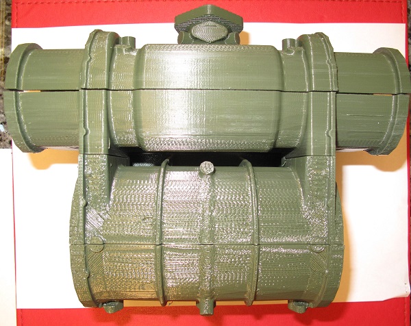
  In order to help our pattern maker, Tony Dance, with the building of the cast cylinder pattern, Phil Yates from the Engineering Committee has produced this 3D model of the motion cylinder and the valve cylinder.

This photo shows the completed structure. At the bottom of the photo is the main driving cylinder. This will have dimensions of 19.5 inch (diameter) × 28 inch (length) (495 mm × 711 mm). At the top is the piston valve cylinder which has a 11 inch internal diameter. The steam input can be seen at the top. The vertical connections are the ports for exchanging live steam and exhaust steam between the motion cylinder and the valve cylinder
   
3D Model of Cylinder (2)
02/03/2018
  Highslide JS
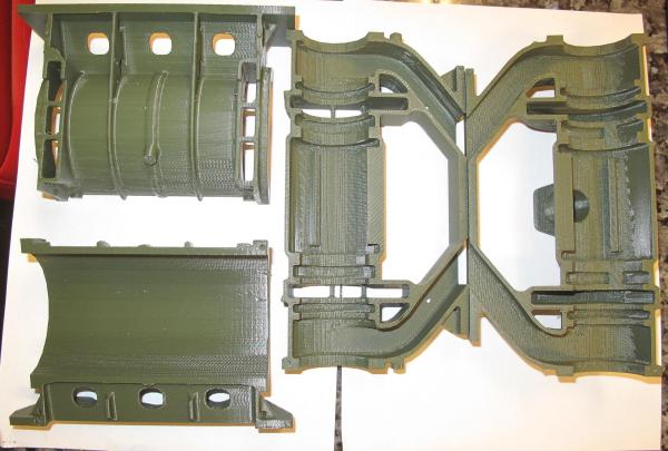
  This photo shows a sectionalised view of the assembly. This should reflect the way in which the pattern is assembled in the casting mould.

The left hand items are a horizontal 'slice' through the motion cylinder. The motion cylinder contains the main piston which is connected via the piston rod to the connecting rod and then to the driving wheels. This is where the locomotive's driving force comes from - maximum piston thrust is 67196 lbs which is just under 30 tons. The bottom left item is the bottom of the motion cylinder. The cylinder is attached to the frame using the flange at the bottom. The top left item is the top of the motion cylinder. At the left and right are transfer ports to exchange steam with the valve cylinder.

On the right is the valve cylinder, sectionalised horizontally. The diagonal passages are the exhaust steam passages which take exhaust steam to the exhaust steam spider, located between the frames and then to the blastpipe.The right hand section has the central live steam input

Whereas the motion cylinder has a single piston, the valve cylinder has a piston at each end connected together via a shaft. The job of these pistons is to cover/uncover the various ports at the appropriate time
   
Frame Components ready for Assembly
08/03/2018
  Highslide JS
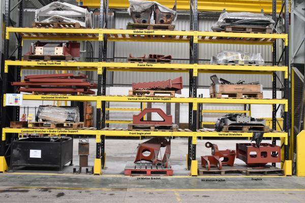
  On a visit to CTL Seal, we were able to see a number of the frame components stacked ready for assembly