For most of the photos on this page, you can click the image for a larger picture.
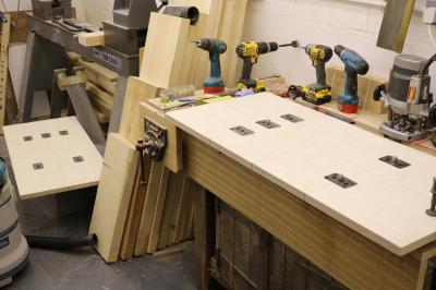 |
With the motion cylinder pattern assembled, Tony has now started work on the valve cylinder pattern. If you look at the first photo on page 1 you will see that the valve cylinder sits above the motion cylinder. The valve cylinder has an internal diameter of 11" and it's job is to control the entry and exit of steam into and out of the motion cylinder. The starting point for the pattern are the 2 parting boards which you can see in the photo. With their locating pins and rapping and lifting inserts, these 'first step' items form the backbone of the valve cylinder sections. As with the motion cylinder, there are four quarters forming two halves which join together longitudinally to make up the cylinder which, with the core prints added are well over five feet long.
The motion and valve cylinder are connected to the cylinder flange plate (see page 1) via a set of ribs. Whereas making the cylinder patterns is a wood turning exercise, these parts involve hand wood working where, in the main, each piece is built up as a laminated item and then worked by hand to Keith's drawings with additions by Tony for 'draw' and added bits for jointing to each other piece of the particular section that he is working on. Tony has had the flange plate drawings printed to full size at a local printer and will be starting this part of the pattern soon. |
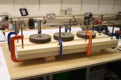 |
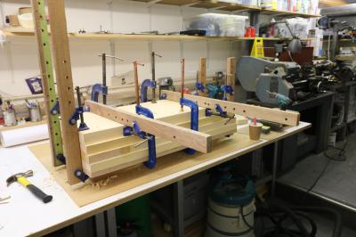
Tony has now commenced the first layer of the first quarter of the valve cylinder blank for turning. For each quarter there will be five layers and one layer is completed over a 24 hour period when the steel screws, currently clamping the layers during the glue curing process, will be replaced by wooden dowels in exactly the same manner as the motion cylinder. |
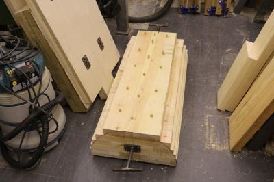 |
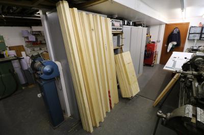
The first quarter of the valve cylinder is now glued up and dowelled with five layers. The second quarter (parting board stood upright next to it) has the first of the layer on and another couple of layers will go on over the next few days. Next, Tony will start on milling the new batch of Canadian Yellow Pine, recently delivered, down to 50mm thick and some one inch boards down to 25mm. This off sawn timber comes as an import and the nominal 10 x 2 and 10 x 1 sizes allows him to mill down to 50 mm and 25 mm respectively. Size is really only important just now during the layering process of these cylinder blanks and once he starts on the other sections, the ribs and flange sections for instance, it's not so important as each piece is laminated and milled down as required. Tony is very lucky as he is not far from a major importer of hard and soft woods and the delivery is free!! |
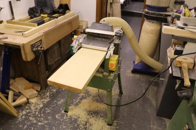 |
Tony reports "As with any job, off cuts tend to gather and today I decided to gather them up and mill them all down to the layer thickness for the next two layers. I spent an hour on the planer and cleared out a number of bits of Canadian Yellow Pine that have been lying around from previous patterns. I've probably gathered enough for the next two layers! The first layer is also now dowelled and that lets me get a flyer for the next layer tomorrow. When that's set in position I'll have a couple of hours on the planer sizing recently delivered 'off saw' planks down to 50mm thickness ready for layers four and five."
Tony is aiming to get the first half of the valve cylinder onto the lathe in the near future. |
 |
4 June - Final layer on the second quarter of the valve cylinder was dowelled up this afternoon. Last Friday ten 6' lengths 10" x 2" of 'off saw' yellow pine were milled down to 50mm, two of which have been used in completing the second quarter of the valve cylinder, the remaining lengths will be used for the next two quarters which I'll work on when the first two are on the lathe. |
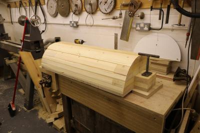 |
12 June - Tony reports "That's the first quarter of the valve cylinder completed and rough planed down ready for mounting on the lathe. The gismo at the end of the blank is a temporary lifting T handle. There's one at the other end of the blank so two of us can mount it on the lathe bed." |
 |
12 June - Final layer on the second quarter of the valve cylinder was dowelled up this afternoon. Last Friday ten 6' lengths 10" x 2" of 'off saw' yellow pine were milled down to 50mm, two of which have been used in completing the second quarter of the valve cylinder, the remaining lengths will be used for the next two quarters which Tony will work on when the first two are on the lathe. |
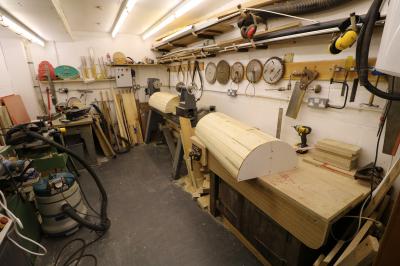 |
14 June - The first 2 quarters of the first half of the valve cylinder pattern have been rough planed to shape and are ready to be joined together and mounted on the lathe. |
 |
Up to now, Tony has been working on the patterms that will generate the outside of the motion and valve cylinders. Making these patterns involves making a male pattern, so that a female pattern can be created in the moulding sand which in turn creates a male casting.
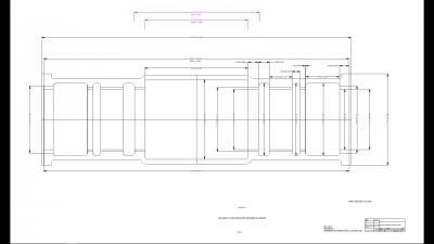
He's now starting to think about the "holes" that will be required in the cylinder casting. For example, we will need a 19.5" diameter hole through the centre of the motion cylinder. To make that he will need to produce a female pattern to produce a male sand "core" supported by "print" extensions that will locate the core in the mould. The molten iron will flow through the gap between the primary pattern and the core to produce the final casting. Making life that bit more difficult is the necessity to produce various transfer ports and galleries in the valve cylinder pattern as can be seen in the drawing. The drawing has been adjusted to allow for shrinkage of the molten metal. The drawing also has to allow for extra material so that the casting can be machined down to the final dimensions. A complex job! |
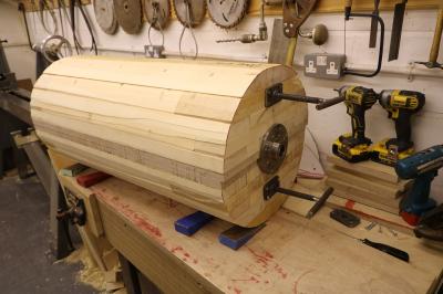 |
Tony has finished the 2 patterns that make up half of the valve cylinder pattern. He's had to set out his lathe at just about max length. Tony says "The blank is on the lathe now but one of the split faceplates is not at right angles to the bed plate so I'm going to de mount the blank and replace the screws with set screws. With these set screws in position, I'll remount on the head and tail stock and use an 8mm flat ratchet to adjust until 'square'. Normally I would do this by adjusting the screws but the end of the blank is very close to the head stock bearing housing." |


