hra fb twitter
sheffield
header

Main Cylinders

First First Previous Previous uparrow Back to Index Next Next Last Last
143 records found. Page 10 of 15 displayed.

For most of the photos on this page, you can click the image for a larger picture.

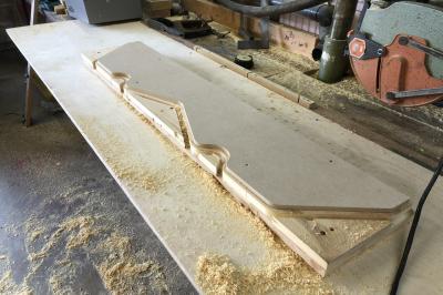
Highslide JS Part way through routing and you can see the final form of the flange pattern.
Highslide JS Job done! The final job will be to apply a slight taper (pattern makers "draw") to the face of the pattern so that it can be easily extracted from the mould. One the cylinder is cast, this face will be machined flat.
Highslide JS December 2020

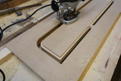
The flange (that bolts to the frames) will be in 4 sections to match the 4 pattern sections. Tony felt that he could improve the method of making the flange patterns. Instead of using an open template and routing round the outside of it, Tony has had this closed slot template made out of MDF. He says that "When cutting a square corner, skill is still required as the direction of cutter travel changes.". Here you can see the router in action.
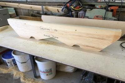
Highslide JS December 2020. Here is the section of the flange pattern after routing. The "lands" or raised sections on the edge will be planed off and the final job will be to plane the face of the pattern to create the angled "draw". In order to pull the pattern out of the sand mould, vertical faces need to have a slight taper angle.
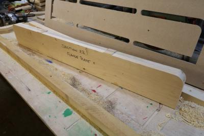
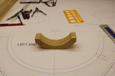
Highslide JS The next big job will be to make the patterns for the "cores" that will be need for the motion and valve cylinders. Remember that the core pattern is a female to produce a male core sand mould which will be supported by extensions called "prints" which will support the core in the main mould. For the main cylinder pattern, this can be produced by turning in a lathe. The core represents a different problem in that concave curves are needed so an alternative to the woodturners lathe is needed. Tony has been experimenting and has come up with this solution. The wooden block in the photo is a scaled down version of what is required. Tony will get a jig manufactured - similar to the one above used for the flange plates - and will produce a series of sections. He will add "tenons" to the shape to locate into the rim of the cylinder and the flange plate. As each section is glued together, the grain will be reversed to the section being glued to.
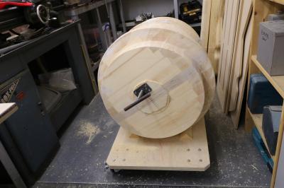
Highslide JS This is half of the motion cylinder pattern off the lathe with the lathe mounting extensions sawn off. This the "print" end which will create a void in the sand mould so that extensions on the motion cylinder "core" can be located in this void. Tony has trimmed off the other end so that the 2 halves of the pattern will mate together using the cone and socket joint.
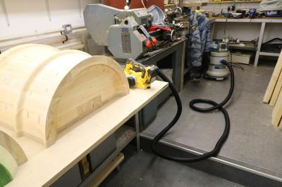
Highslide JS Here is the socket end after cleaning up with the power sander
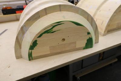
Highslide JS And the male cone end of the pattern
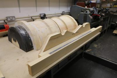
Highslide JS The 2 "quarters" on the bench with the flange pattern alongside
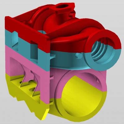
Highslide JS A reminder of the layout of our pattern. Each colour represents one of the 4 sections of the pattern which will be built up as layers in the sand mould. Looking at the flange plate on the left, we can see the 2 holes for the exhaust steam outlets. At the bottom of the flange, we have a large void with strengthening ribs - this will be to reduce the weight of the casting. We will need to create a "core" here to produce this void. That core will need "prints" to support it.
First First Previous Previous uparrow Back to Index Next Next Last Last
143 records found. Page 10 of 15 displayed.