News Archive entries for July 2020
Here are the diary entries for this month. You can use the forward and backward links to see the next or previous months. Most photos taken before 2018 are small size. From 2018 onwards, most photos you see below will have a link to a full size image by clicking on the photo.
| Sandboxes added to 3D Model |
| 02/07/2020 |
| |
 |
| |
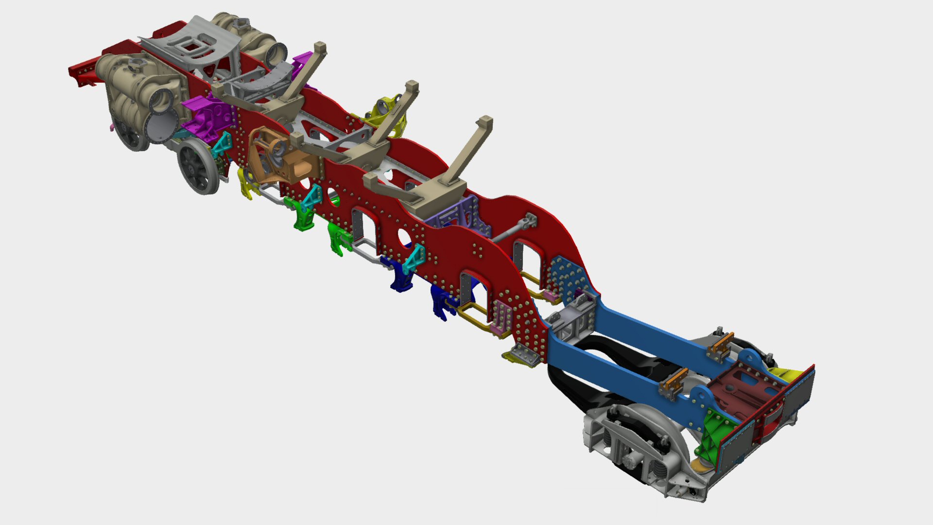
Keith, our 3D CAD expert, has been busy and has added the sandboxes to the 3D model. The rear sandbox is bigger than the front 2 sandboxes as it provides sand to the rear of the centre driving wheel (for rear direction running) and sand to the front of the trailing driving wheels (for normal running). The sand filler pipes (square section) fit close to the boiler so the final welding of the filler pipe to the sandbox flange will only take place once the boiler has been fitted. |
| |
|
| Cylinder Drain Cock Bracket |
| 06/07/2020 |
| |
 |
| |
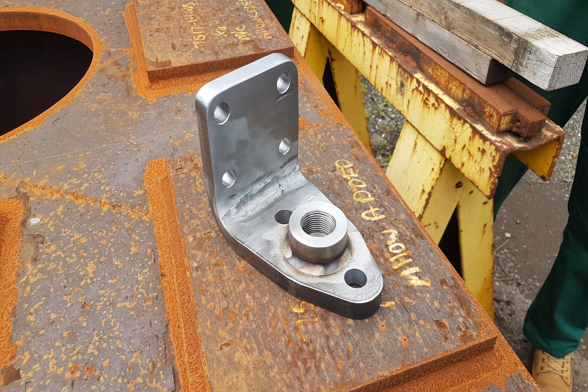
Did you know that a "Clan" locomotive has 2 cylinders and 5 cylinder drain cocks? The normal place for the cylinder drain cock is one at each end of the bottom of the cylinders. When the engine is standing, steam can condense to water within the cylinder. Any attempt to compress this water would result in the end covers being blown off. So the cylinder drain cocks are opened when starting to move off - the resulting steam cloud ruins the photo you've been trying to take. The fifth cylinder drain cock is mounted on this bracket which we picked up today from Alpenbury Engineering in Rotherham. The bracket is bolted to the outside of the frames on the right hand side, just behind the centre line of the trailing bogie wheel. It's purpose is to provide the smae drain function for the superheater header which is mounted on the front face of the front boiler tube plate. A 1 inch pipe comes down from the header and the drain cock is activated with the other drain cocks. |
| |
|
| Rubbing Plate Liners |
| 13/07/2020 |
| |
 |
| |
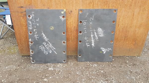
Another example of the myriad of minor parts that go into a steam loco. These are manganese steel liners that will be riveted to the rubbing plates which are, in turn, fastened to the hind beam. Powerful dumb buffers fitted to the front of the tender frames press onto these plates. The springs were a modification to the original design of the Class 7 Britannias - on the Great Eastern when the restaurant car was behind the loco, "stained tablecloths and slopping saucers became synonymous with Class 7 Haulage"! (Bill Harvey - 60 years in Steam). Managanese steel is very hard wearing - not appreciated by the machinist who had to work on them. |
| |
|
| Bracket for Vacuum Dummy Coupling |
| 13/07/2020 |
| |
 |
| |
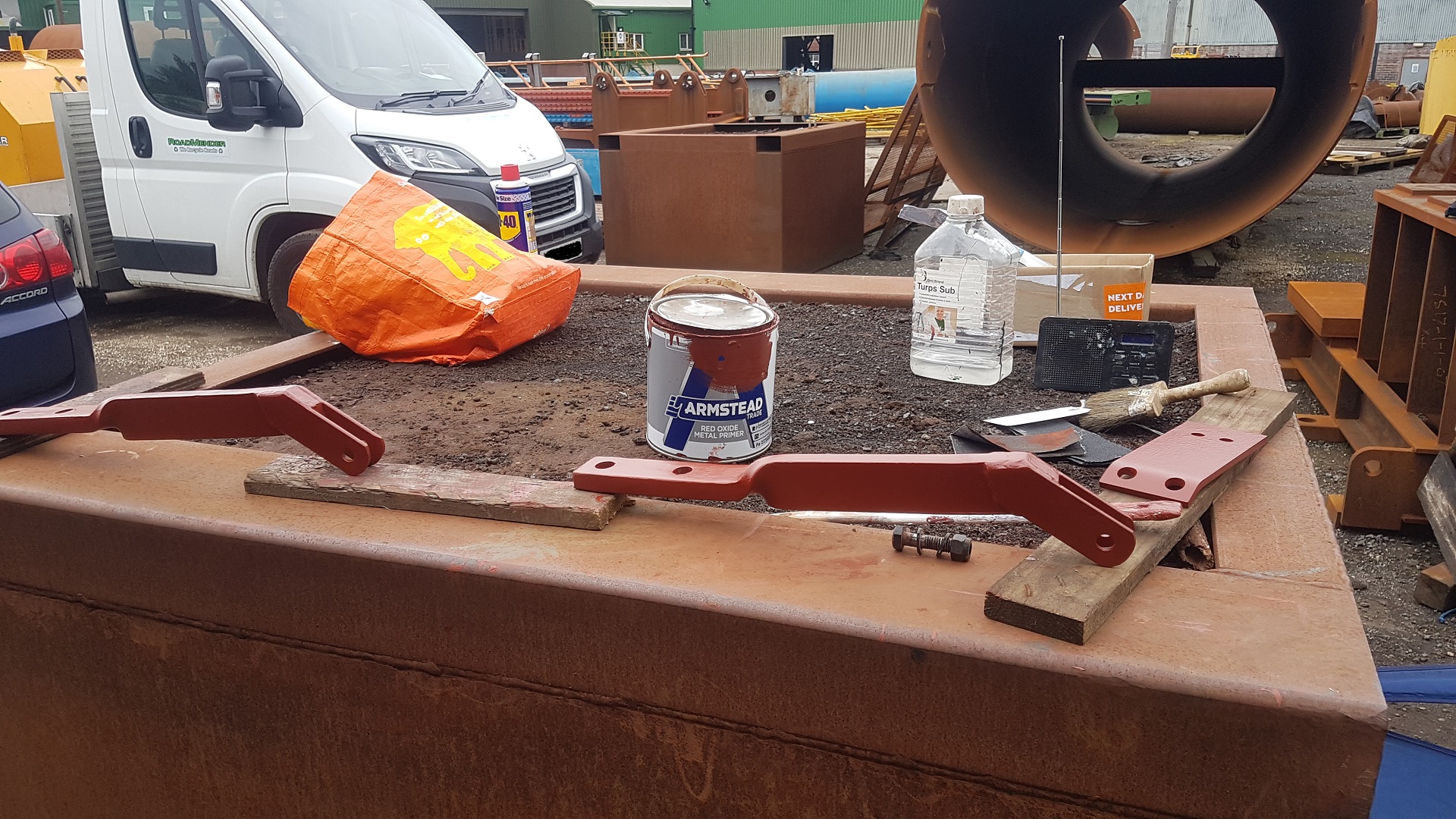
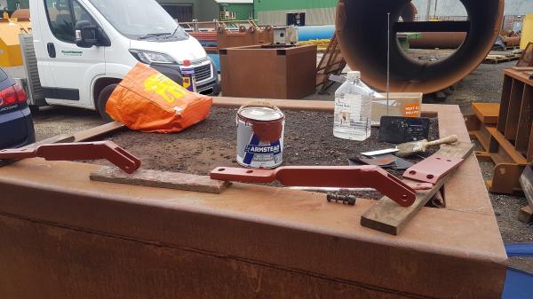
Ashley has been busy with his paint brush again. The 2 brackets are the Bracket for Vacuum Dummy Coupling. We need on on the front of the loco and one on the rear of the tender. When the vacuum brake hoses are not connected to a train, the are connected to a disc plate on these barckets to seal the pipe. This allows the vacuum to be created so that the brakes can be released. On the right hand side of the image is a small angled bracket. This secures a pipe going from the cab to the vacuum reservoir between the frames |
| |
|
| Buffers |
| 20/07/2020 |
| |
 |
| |
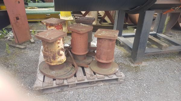
We this set of buffers moved up to the container today. We have 2 oval head buffers and 3 round head buffers. The oval head buffers are surplus to requirements as we have 2 more in the assembly shop waiting to be fitted to the buffer beam. 2 of the round head buffers will be required for the tender so 1 is surplus to requirements.The surplus buffers have now been sold. |
| |
|
| Small Parts |
| 27/07/2020 |
| |
 |
| |
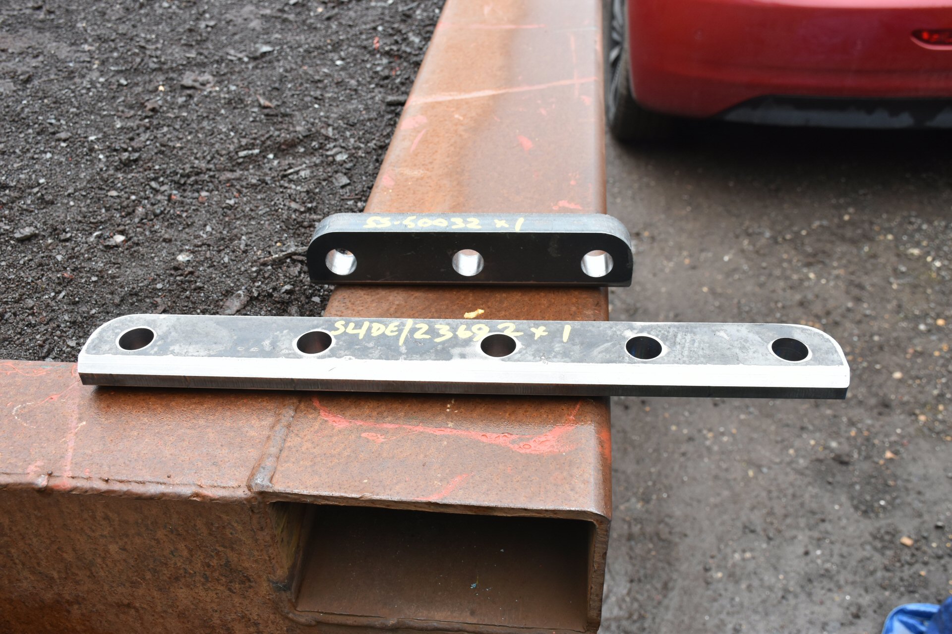
Small parts have important roles to play. British Railways Automatic Warning System was retrofitted to the Britannias and the Clans in the period 1959 - 1962. One of the components was a receiver mounted on a stay on the front of the bogie. To protect the receiver from the coupling, hanging from the drawhook on the buffer beam, a rectangular plate was attached to the bottom of the buffer beam. The 5 hole section in the image is the mounting bracket for the plate and needs to be welded to the bottom of the buffer beam. The 3 hole plate will be a modern day modification. Again, this will be welded to the bottom of the buffer beam. The bracket for the air braking shut off cocks will be attached to the plate |
| |
|