hra fb twitter
sheffield
header
Rail200

Frame Assembly Phase 1

First First Previous Previous uparrow Back to Index Next Next Last Last
82 records found. Page 7 of 9 displayed.

For most of the photos on this page, you can click the image for a larger picture.

Highslide JS May 2022

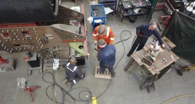
From above, it can be seen that the gussets are in place together with the steel angle that will support the platform plates.
Highslide JS June 2022

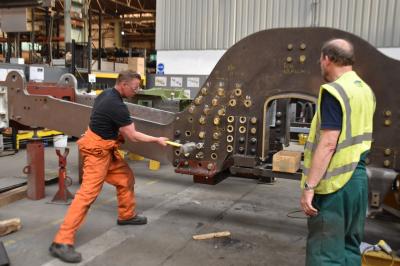
The fitted bolts are designed to be a Heavy Drive so it takes some effort to get them to fit. A thick copper pad has been taped to the head of the fitted bolt and Lee from CTL Seal drives them in with a sledge hammer. A distinct change in noise signifies that the head of the bolt is firmly against the frame plates.
Highslide JS July 2022

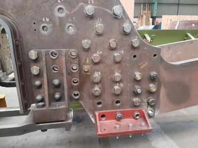
Progress with the fitted bolts joining the main frames to the frame extensions
Highslide JS September 2022

With virtually all of the bolts fitted, we now need to check the position of the trailing spring hanger bracket before drilling and reaming the bolt holes to final size. The fore and aft spring hanger "toes" need to be equidistant around each axle centre line. Mike is checking the dimensions with a plumb bob suspended from the axle centre line.
Highslide JS October 2022

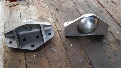
A large part of building a locomotive for main line work is paperwork. These are the bogie bolsters that are bolted to the front of the locomotive frames and transfer the weight of the front of the engine to bolster cups on the bogie frame. We had a pair of bogie bolsters that were manufactured many years ago but there was no associated paperwork. Therefore the decision was taken to manufacture new bolsters. These were cast and machined by Furniss and White in Sheffield.
Highslide JS October 2022

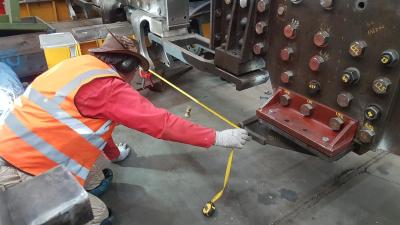
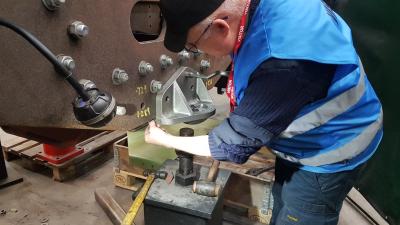
The first job was to fit the bolsters into position and check that they butted up cleanly against the bottom face of the frame pad. John is checking with a feeler gauge.
Highslide JS December 2022

The fixing bolts for the bolsters go through the bogie bolster, the main frame plates and the bogie pivot stretcher. The holes in the stretcher had not been drilled, so the drilling and reaming job involved :-

  • The holes in the bolster were 15/16" diameter.
  • Use a 15/16" twist drill to correctly locate the magnetic drill.
  • Drill a pilot hole through all of the plates with a 3/8" drill.
  • Drill through all of the plates with a 25mm twist drill.
  • Finish with a 1" reamer.

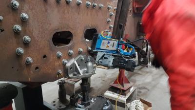
Mike H is drilling the pilot hole with the magnetic drill suspended from one of the overhead cranes.
The BR drawings show that the bolsters were secured with cone head bolts, with the bolt heads on the inside of the frames. As these are fitted bolts, we will need to jack in the bolts as it will be impossible to wield a hammer in the restricted space.

Highslide JS January 2023

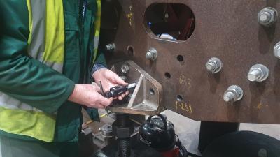
Geoff measures the hole diameters with a Bowers gauge so that we can specify and order the bolts.
Highslide JS January 2023

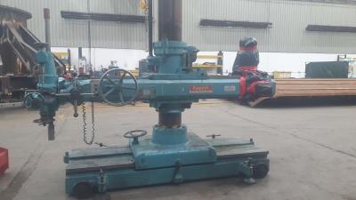
We have acquired an Asquith "portable" drill to help us drill holes. The spindle was slightly out of true. Fortunately, the Asquith company is still in business and they were able to straighten it out for us later in the year.
Highslide JS April 2023

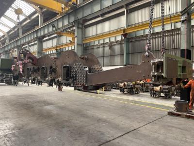
April saw a reorganisation of the CTL Seal assembly shop with the frames being moved to a new position in the shop.
First First Previous Previous uparrow Back to Index Next Next Last Last
82 records found. Page 7 of 9 displayed.