Front Bogie
For most of the photos on this page, you can click the image for a larger picture.
 |
October 2022
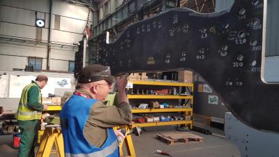
Work has started to assemble the bogie frame. The central stretcher has been placed upside down on trestles. The first job is to ensure that the top machined surface of frame plates is bedded into the corresponding machined surface of the stretcher. Here John is getting purple fingers by applying engineers blue to the machined surface of the frame plates. |
 |
October 2022
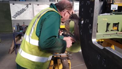
Once the frame plate has been lowered onto the stretcher, it can be removed to check for high spots as shown by the engineers blue. Here Geoff is inspecting the surface. |
 |
October 2022
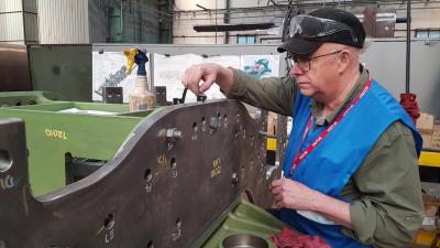
The frame plates are secured to the stretcher using temporary bolts. With the bolts fully tightened, John checks for fit with a 1.5 thou inch feeler gauge. As you can see, the feeler gauge has bent showing that the plate is sitting firmly against the stretcher. |
 |
October 2022
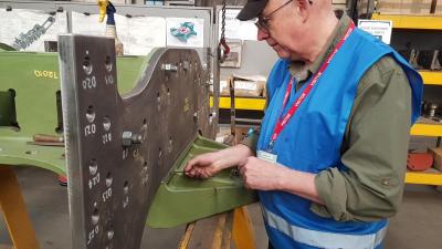
The same test is repeated at the horizontal surface between the frame plate and the stretcher |
 |
October 2022
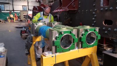
On the cannon axleboxes, Ashley paints the end covers with top coat. Again, these will be difficult to paint once the wheel is assembled on the axle. |
 |
November 2022
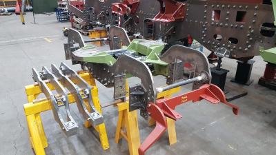
For our Annual General Meeting, we prepared the bogie frame components for display. The cannon boxes had been delivered to South Devon by then. |
 |
November 2022
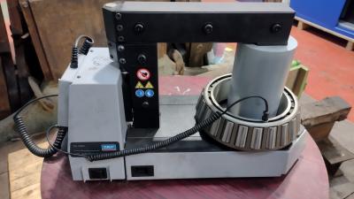
Down at South Devon Railway Engineering, work started on assembling the cannon boxes. An induction heater has been used to warm and expand the bearings so that they will slip easily onto the axle. |
 |
November 2022
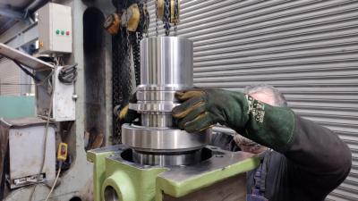
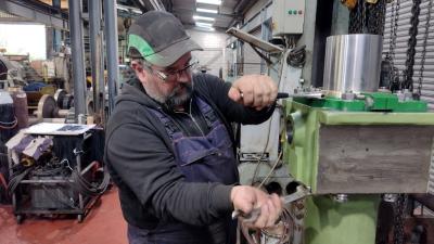
The cannon box is placed and secured in a vertical position and the axle assembly is lowered into the cannon box |
 |
November 2022
With the axle in place, the end covers are bolted into position |
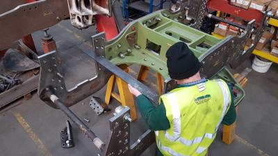 |
Back at CTL Seal, Geoff is using a large and heavy square to check that the axlebox faces are truly in line. They were! |


