Main Cylinders
For most of the photos on this page, you can click the image for a larger picture.
 |
February 2023
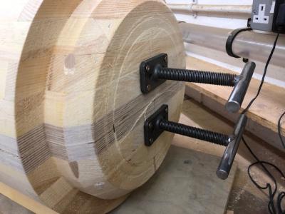
Tony says "I'm in the process of template making for the steam chest for the second half which is on the lathe. Pics attached of lifting pins being added to the first half so I can lift half of that to sit on top of the drawing." |
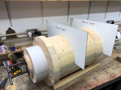 |
Tony continues "This is a check I'm on size and make the last of the templates for the three main diameters. Templates are made of white faced hardboard from previous jobs used as drawings for castings currently on running locomotives. This helps my recycling profile. !!
The profiles for the steam chest, valve chest and other shapes are already done from last time."
|
 |
April 2024
Work has recommenced on the manufacture of the cylinder patterns. Tony explains
"I've enlisted the aid of another pattern maker to hep me complete what’s required to produce the cylinder patterns. To accomplish this, I have moved the pattern making side of my workshop machinery to the workshop of Ruth Davies, a master pattern maker and wood carver.
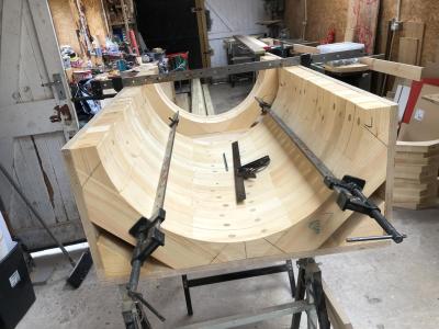
The photo is the 1a core box now fastened up waiting for Ruth to finish off the ends. We’ll add some pieces to the undersides to sit well on the foundry floor and a number of drop down lift handles as the finished box is quite a weight. They will also take the lifting strops in the foundry."
The 1a corebox is the bottom of of the main cylinder corebox. The core box will be the whole length of the main cylinder plus the core prints ( remember coloured in black) and the draft to allow the core to be removed from the core box. This draft also helps the moulder when settling the core in the mould sand. The core prints you will remember are the extra bits external to the pattern to allow a core to be correctly located in the hole left when the pattern proper is removed from the mould sand. If you go back to page 11, first photo, you can see the black extensions on the main cylinder pattern. These create rebates in the sand mould - the prints on the core will locate in these rebates.
Tony will modify this corebox to create additional inserts to create the 1b core with the transfer port cores (see previous page) |
 |
June 2024
The next 4 entries are general pics of a working pattern shop. We're currently working on the lower section of the main cylinder core box The end caps are now complete and the fasteners added. The end caps have draft of about 3/16" built into them to allow the core to sit snug in the mould of the main cylinder pattern which also has same draft. In this case we've made the end caps removable, and the moulder will probably turn the whole box upside down, remove the end caps, knock the bottom and lift the core box off. We're also adding four handles to allow the box to be lifted off the core or generally carried.
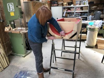
In the photo, Ruth is adding final pieces to achieve the correct overall length of the cylinder core plus the core prints. |
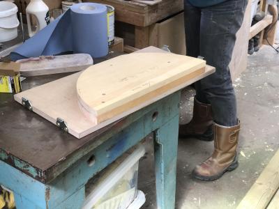 |
End piece with clips |
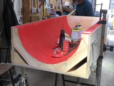 |
Box ready for end cap |
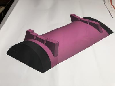 |
Next jobs are to draw up the core loose pieces for the steam transfer ports. The ports are not angled, it's just the way the drawing was laid out for the photo. |
 |
We're on the final stages of the MMC core and adding the core box loose pieces. Although this is a split core box, we are only using one half which can be modified by the addition of two loose pieces to make one half box able to make up the whole main centre core section through the cylinder. The bottom half is a simple semi circle whereas the top half needs to have the transfer ports that allow steam to pass between the valve cylinder and the main cylinder.
These loose pieces, therefore, are required to modify one half of the cylinder core to accept the two steam transfer port cores and it’s a modification to the core box and not, as usually is, parts of the cylinder pattern which, could not be removed from the mould in a straight withdrawal of the pattern from the mould sand. Tony says "As the time goes on, we’ll see more and varied loose pieces and its these pieces which make pattern making fascinating."
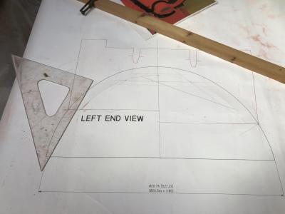
In the photo, the loose piece (in red) is added to the cylinder cross section drawing. |
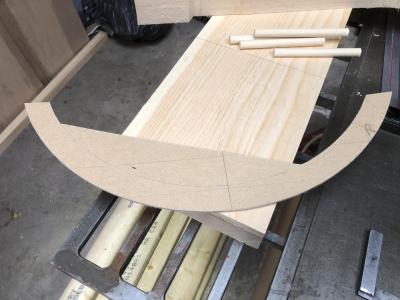 |
A template is made up from the drawing. |
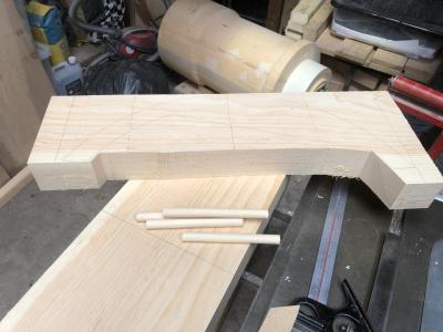 |
A block of wood is ready for drilling of the holes for the dowel locating pegs which go through the loose piece vertically into the core box. |


