Main Cylinders
For most of the photos on this page, you can click the image for a larger picture.
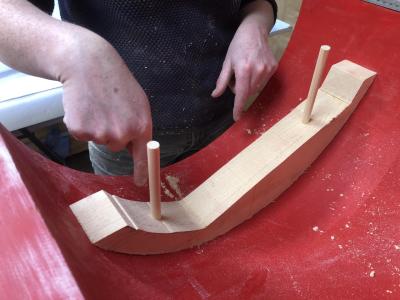 |
Finally with loose piece in position shaped only to be located in one position, i.e. Off centre pins of differing centres |
 |
June 2024
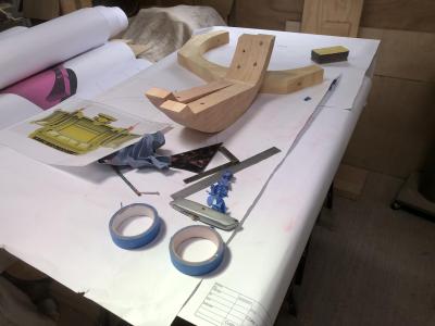
Ruth is using the cross section image from our 3D model to design the loose pieces for the transfer ports that convey steam between the steam chest and the main cylinder. Corresponding loose pieces will be required for the steam chest core box and a joint between the 2 sets of loose pieces will be required. Having settled on the shape of the steam transfer ports loose pieces, Ruth is now working on the final shape of the joint between the upper and lower section cores. The main pattern join, has a locating step at these points but Ruth thinks, from a foundry point of view, the core would be better without a step to ease the core production method. |
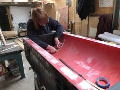 |
Tony and Ruth have made the final measurements of the motion cylinder core box against the pattern, confirming that the dimensions were spot on. |
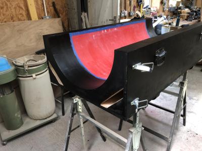 |
To finish off the job, the core box was filled where necessary and painted. |
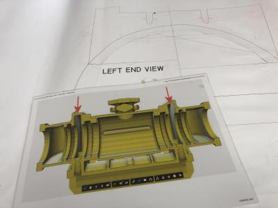 |
Tony is starting work on the core box for the steam chest. The steam chest is the elongated cylinder that is positioned above the motion cylinder. Starting from the left hand side, the section shows
- The exhaust steam port where exhaust steam is conveyed to the blastpipe and chimney.
- A ribbed area where the cylindrical liner for one of the valve spindle pistons will be located.
- The central steam chest where live steam from the regulator is introduced. The horizontal rib is to prevent the piston rings from springing out as the valve spindle is removed during overhauls.
- A second ribbed area where another cylindrical liner for the other of the valve spindle pistons will be located.
- Another exhaust steam port where exhaust steam is conveyed to the blastpipe and chimney.
Tony says "This will take the lines of the motion cylinder core box (mccb), routing solid sections of timber instead of using pliable mdf or other materials. In the steam chest core box case this timber will be birch ply. I also want to use the same method as the mccb by only using one main box with the unequal section exhaust channel core sections added separately." |
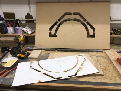 |
Tony will use the same system as used for the mccb with multiple "U" sections joined together. Whereas the mccb was a constant diameter throughout, it can be seen from the drawing above that the steam chest core box involves U sections with different diameters and different thicknesses. The image shows a trial run with one of the three diameter templates for routing. |
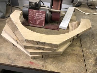 |
Here's a run of sections for the largest diameter of the steam chest centre section. |
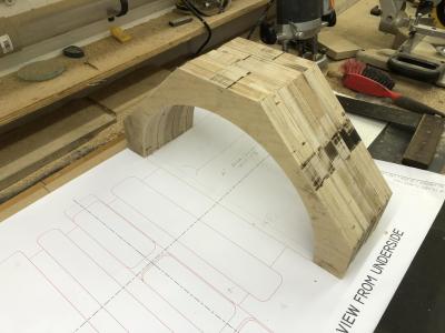 |
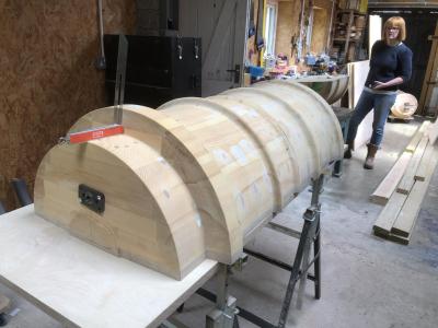
This shows general set up as sections with different diameters are added. The Length OverAll of this box internally, which includes the two prints and the end cap location space is around 70 inches. Tony will need to produce 70 routed sections to make the core box. |
 |
July 2024
Due to the length of the pattern, Tony has had to split the pattern vertically. Now its time to join the 2 halves together. Here the 2 halves have been set up ready for joining. |
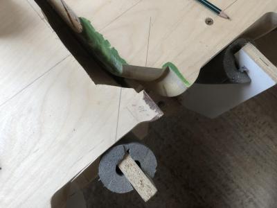 |
The 2 halves have a taper and socket joint system to ensure a firm connection. |


