Main Cylinders
For most of the photos on this page, you can click the image for a larger picture.
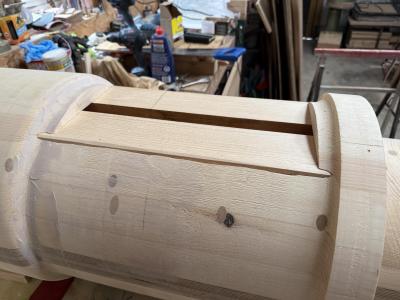 |
This was the position after the first two pieces of new timber were fitted. Only the top piece to fit. |
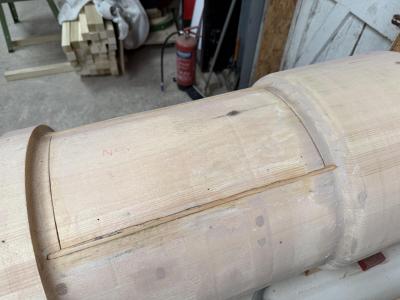 |
This is the repaired valve cylinder pattern ready for some filler. You can see how the new timber added is just poking through and Ruth will now be able turn this down when the cylinder section is returned to the lathe. |
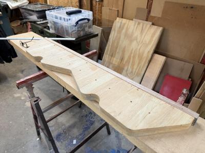 |
Having repaired the valve cylinder pattern, Tony is now moving onto the next job.The cylinders have a flange plate which is used to bolt the cylinders to the frames - using 45 1.125 inch (28.5mm) bolts per side. As Tony is splitting the cylinder pattern into 3 horizontal sections, the flange plate needs to be in 3 horizontal sections. Tony wants to start making up the flange plate to size and adding or removing material to add the double draft for the three-flask mould. The draft is the necessary vertical taper so that the pattern can be removed fro the sand mould.
These sections of the flange material are double laminated and reinforced with a single or double hardwood strip. The hardwood edges of these will have pattern maker's locators added, similar to the halves of the motion and steam chest sections. |
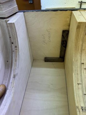 |
The cylinder pattern will end up being like a large 3 dimensional jigsaw comprising of the wooden patterns and core boxes. Some parts of the pattern will be "loose pieces" as separate wooden parts. Tony needs to design how all of the various pattern parts can be removed from the sand mould. Tony says "I've thought out and drawn up the method of using two sets of two loose pieces of different sections which are interchangeable to match the steam exhaust to spider ports. The photo shows one of the loose piece locations. One half of the core will be made up with one set of loose pieces and the other half will be made up with the other set. There are other loose pieces to be added but I haven't worked out how to do these yet. I'm working towards both valve ends being complete and fastened up and the steam chest being made up but not fastened in the box until I work out how to make the other loose pieces to accommodate the lands for the cylinder liner."
As the same core box will be used for both halves of the core, two loose pieces will be inserted for the first half and then swapped with another two loose pieces when making up the other half of the core.
The right angled piece is a square and this will be the position of the loose piece for the exhaust passages. The void where the square is sitting is where the foundry Moulder will add the loose piece. |
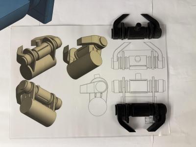 |
This photo shows the full core system for the cylinder pattern. It shows the main motion cylinder, valve cylinder and steam chest, the two steam exhausts to the exhaust spider, the two inlet and exhaust ports between the main motion cylinder and the valve cylinder and steam chest and the main steam inlet. The two black printed sections are a 3d printed model and are the core sections I am making at the moment. |
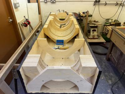 |
4 March 2025
This is the current situation of the valve cylinder/steam chest core. Tony says "I hope by the end of next week to have most of the sections routed and in position." |
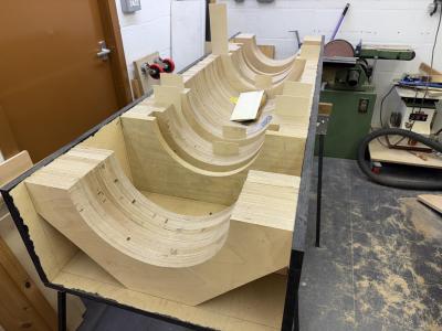 |
11 March
Tony reports that all steam chest core box sections are complete - there are 72 sections in all. Next job is to make the loose pieces that will go in the 32 gaps and also provide the exhaust steam passages. |
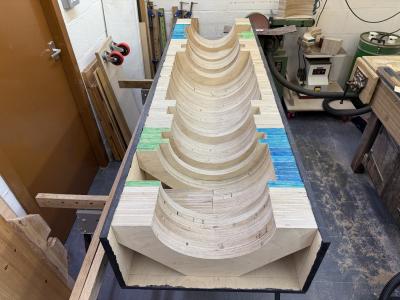 |
This is the steam chest/valve cylinder core box nearing completion of stage 1. The steam chest (where the live steam enters the casting) is in the centre, the valve cylinders either side. Remember that the core is used to create a sand "plug" that creates the air spaces in the casting. Tony will create 2 sand plugs that will be joined together to make a circular sand plug from the single core box. However, Tony now faces a challenge for stage 2. The complete core needs to include the exhaust port passages (see next photo). The exhaust passages connect to the valve cylinders in the blue/green shaded areas. |
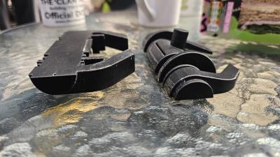 |
Back to the 3D printed model of the core. The model represents the sand plug that needs to be created by the core box. The round extension in the centre is the steam inlet. If you look at the exhaust port passages (going to the right) you will see that the top section is shallower in depth than the bottom section. Tony now needs to make "loose pieces" that will convert the core box into a upper core box and a lower core box. |
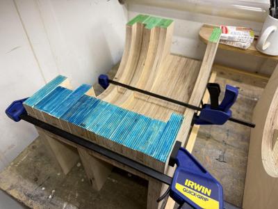 |
These are the two completed loose sections to change the bottom section of the valve cylinder core box above, to produce the top half of the core illustrated by the black printed model. |


