hra fb twitter
sheffield
header
Rail200

Main Cylinders

First First Previous Previous uparrow Back to Index        
210 records found. Page 21 of 21 displayed.

For most of the photos on this page, you can click the image for a larger picture.

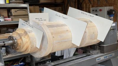
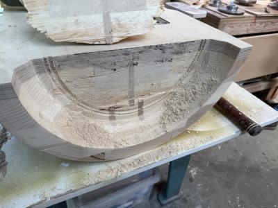
Highslide JS The second half of the valve cylinder pattern has been checked for correct dimensions using templates. The BR Standard Pacifics use inside admission of live steam into the steam chest. On either side of the central steam chest are the valve cylinders controlling the input of live steam into and exhaust steam out of the main cylinder. The core print is the extension of the pattern which will form a cavity in the sand mould. The ends of the core "sand plug" will rest in this cavity to ensure that the core sits centrally in position.
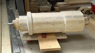
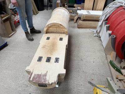
Highslide JS This is the completed second half of the valve cylinder pattern. On the left hand side, Tony will need to remove the block for the lathe mounting adaptor. On the right hand side, Tony will need to form a female cone joint to that it can mate up to the first half (see next photo)
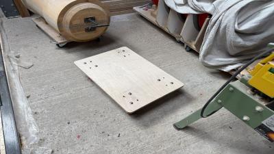
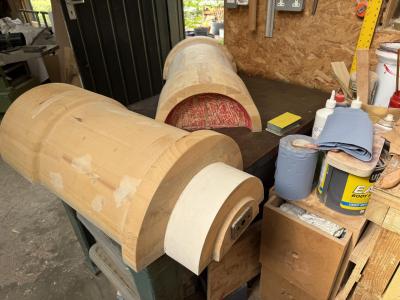
Highslide JS To help with moving these heavy components around, Tony has made a couple of castor wheel trolleys. Note the male cone joint on the first half of the valve cylinder pattern.
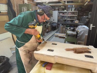
Highslide JS This is Tony at work forming the female side of the cone plug and socket joint that will allow the 2 halves of the valve cylinder pattern to be joined together. Tony is using a long reach titanium saw blade and the oscillating saw. Tony reports that "The blade was superb and perfect for the job."
Highslide JS Job almost complete on this section with a bit of cleaning up to do
Highslide JS August 2025

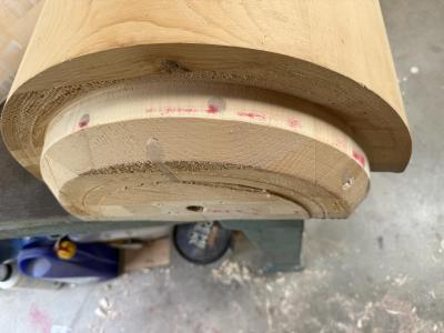
Tony and Ruth have been working on joining the 2 sections of the valve cylinder pattern together. Tony had to produce them in 2 halves due to the length. On the half in the background, red chalk has been applied to the female socket. This will help identify any high spots on the male joint on the half in the foreground. On the latter, the cream extension is the pattern makers "print". This will create a recess in the sand mould which will support the valve cylinder core.
Highslide JS The high spots show up on the male plug which can be sanded down.
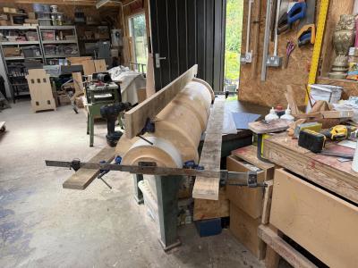
Highslide JS The 2 halves now need to be glued and screwed together. The complete assembly is now placed on a surface plate to ensure that the complete assembly is flat. Cramps are applied and the assembly is left for the glue to dry.
Highslide JS 3 sections of the valve are sitting on the storage cradle waiting for the final section (in top right) to be joined

The metal plates provide locating pins to ensure top and bottom halves are located correctly.
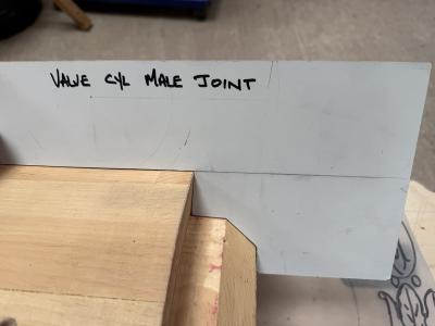
Highslide JS Templates are used to ensure that the plug and socket joints are exactly the correct size. Tony reports "We made such a good job of the mating the joints of the second half of the pattern that we couldn't get a 'squeeze' on the joint due to the glue setting up while we were sorting the pattern pins."

Tony and Ruth will now be turning their attention to the transfer ports.
First First Previous Previous uparrow Back to Index        
210 records found. Page 21 of 21 displayed.