


Loco Dragbox
The dragbox is fitted at the rear of the locomotive frames and is the component that transfers the forces from the locomotive through the drawbar to the tender and then onto the train. 72010's current dragbox can be seen in the picture below, bottom right. The engine dragbox and tender dragbox are connected together by a substantial steel drawbar which is a circular rod 2-3/4" (70mm) in diameter.

Dragboxes are also fitted to the front of the tender frames and the rear of the tender frames.
One of the features of the frame design of the BR Standard Pacific locomotives is that the frames were placed centrally (looking fore and aft) over the hornguides. The hornguides are the inverted "U" cast components fitted to the cut outs in the frame - these constrain the driving wheel axleboxes and allow them to move vertically. By placing them centrally, this ensures that the weight of the locomotive is transferred to the centre of the axleboxes. The consequence is that the frame plates are closer together than other engines and the cylinders sit more away from the frames. Thus the cylinders have more leverage and this can impose a "racking" motion to the train. 71000, Duke of Gloucester, has 3 cylinders (one between the frames) so this motion is not encountered. A long standing problem throughout the life of the Britannia locomotives was the imparting of a "fore and aft" oscillation motion to their trains. This problem was also experienced on the BR Standard Class 5 4-6-0 locomotives.
The oscillation motion problem emerged fairly early on in the service life of the Britannia locomotives. Trials with 70006 Robert Burns were carried out within a month of its arrival at Norwich in 1951. [1] Bill Harvey reported "A high-frequency oscillation of approximately 1/8in persisted throughout the journey...................This unpleasant vibration was transmitted to the restaurant car which at that period was near the head of the train, to the extreme discomfort of the diners; stained tablecloth and saucers slopping over became synonymous with haulage by a Class 7MT." The engine was connected to the tender by a drawbar which was "a spring-loaded design comprising a number of large reinforced rubber pads as copied from LNER designs." [2] The large reinforced rubber pads are known as drawbar springs.
The drawbar drawing is believed to be SL/DE/19683 dated 14 June 1950. The drawing shows an eye in one end for a vertical pin in the engine dragbox and a threaded portion at the other end for the drawbar spring bearing on the tender dragbox. It is assumed that the tender dragbox drawing is SL/DE/20300. SSLC refer to this as the Mk 1 drawbar system.
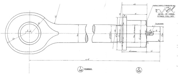
The original drawbar.
On 6 June 1951, the trial train was strengthened to 12 vehicles. This increased the shuttling movement so by the time the train got to Ipswich to take on water " the firemen was standing ankle-deep in coal shaken onto the footplate, and he had no alternative but to shovel this into the firebox in order to enable the cab door to be opened" [1]
Harvey reports "Roland Bond, chief officer for design came post-haste from Derby to see for himself what was happening and as a result the type of intermediate drawgear used by the GWR and LMS was substituted. With this arrangement, locomotive and tender were united by a solid drawbar and kept apart by powerful intermediate buffers; the combined weight of locomotive and tender was sufficiently great to damp down and absorb the disturbing forces set up by the former."
Due to the requirement to use a vertical pin on the tender (as opposed to the drawbar protruding through a plate on the dragbox), the tender dragbox had to be redesigned - drawing SL/DE/20770. This we will refer to as the Mk 2 drawbar system. The engine dragbox is detailed in 2 BR drawings:-
- SL/DE/19619 Hind Dragbox (Fabrication, i.e. welded from plate). This was fitted to most of the Class 7 Britannias and all of the Class 6 Clans
- SL/DE/21599 Hind Dragbox (Casting). This was definitely fitted to 71000 Duke of Gloucester and the drawings shows that it was allocated to Class 7 locomotives, 70045 to 70054.
The cast dragbox was allocated to the Lot 242 Clans. Both drawings were analysed by SSLC and it was concluded that there were no major differences apart from the method of construction. Therefore the dragbox for 72010 was manufactured in 2017 to the SL/DE/19619 drawing.

This is the dragbox for the Mark 2 drawbar system. The photo is looking from the front and the bush for the vertical pin can be seen.
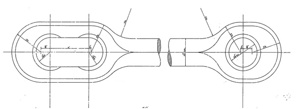
This is the drawbar for the Mark 2 drawbar system which is fixed by 2 vertical pins, one on the engine and the other on the tender to drawing SL/DE/20738. The oval in one eye is to allow some movement as heavy duty sprung buffers fitted to the front of the tender require movement to work.
Research by SSLC in 2021 and 2022 at the National Railway Museum in York involved the minutes of meetings of the Chief Draughtsmen (1950 to 1954) and the Locomotive Standards Sub-Committee (1954 to 1964). Both of these meetings were chaired by E S Cox; they cover building/development of the BR Standard locomotives and the early diesel era. As such, they contain an enormous amount of valuable information as to how the designs developed and were modified.
One aspect that recurs throughout the meetings is the problem of fore and aft oscillation. After the 1951 modifications, the problem persisted not only on the Class 7 Britannias but also on the Class 5 and one of the classes of standard tanks. The first indication that the problem had become serious was when LSSC minutes report in 1957
"None of the foregoing deals with the root cause of the trouble which is due to resonant vibrations of the drawbar springs at high speed. This aspect has been investigated mathematically at Swindon primarily in connection with the Western Region 1000 class locomotives and a change in the characteristics of the intermediate drawbar and buffer springs was found to cure the trouble completely. Similar investigation has shown that the B.R. Class 7 locomotives have the same characteristics which probably apply to other B.R. locomotive types as well. The modifications to bring about the necessary improvement involve a re-design of engine drag boxes and certain modifications to frame and frame brackets. The notional estimated cost of carrying out an alteration to a B.R. Class 7 locomotive as per drawing SL/SW/1087 is £210 per Locomotive." [3]
In 1958, the minutes report "Swindon reported that B.R. Class 7 Engine No. 70028 will be fitted with the new drawgear when it is turned out of shops and operating experience with this drawgear is awaited before further action is recommended." [4]Later in 1958, the minutes report
"Following the introduction of class 7 4-6-2 locomotives on high-speed services over the Midland division of the LM Region, the dragbox of one of the locomotives concerned, number 70044, has become seriously distorted and fractured obviously from the same cause as referred to in Min.764(c). It is RECOMMENDED that this locomotive should now be fitted with the new design of dragbox without waiting for experience with locomotive number 70028 and that the further four class 7 locomotives on the Midland division should be similar dealt with in due course." [5]
In January, the new design has been tested and the minutes make a recommendation:-
"(864) INTERMEDIATE DRAWGEAR. (Previous Minute 835)
In connection with the fitting of an improved design of intermediate drawgear and dragbox to overcome the possibility of serious resonance disturbance at high speeds, the following sets out the present position.
(i) Swindon report that locomotive no. 70028 fitted with the modified arrangement has now run over 1200 miles without any adverse reports.
(ii) There is no doubt that resonance can occur under certain circumstances at the higher speeds with the exist design of intermediate drawgear on certain classes of B.R. locomotives. This may result in appreciable damage to the dragboxes etc.
(iii) Previous Minute 835 recommended that the five Class 7 locomotives operating on the Midland Division of L.M. Region should be fitted with the modified arrangement. It is understood that arrangements are now in hand to fit one of these locomotives under experimental procedure.
It is RECOMMENDED that it should be left to each Region whether there is a case for fitting further class 7 or any 6 locomotives with the modified arrangement, having regard to maximum speeds called for in their rostered duties." [6]
Although the minutes make a recommendation, it is left to the regions to decide whether to implement the change or not. In 1959, the future of steam was limited and it might be expected that this recommendation was not actually implemented. However, it has been established that both 70000 and 70013 have been fitted with this Mark 3 drawbar system.
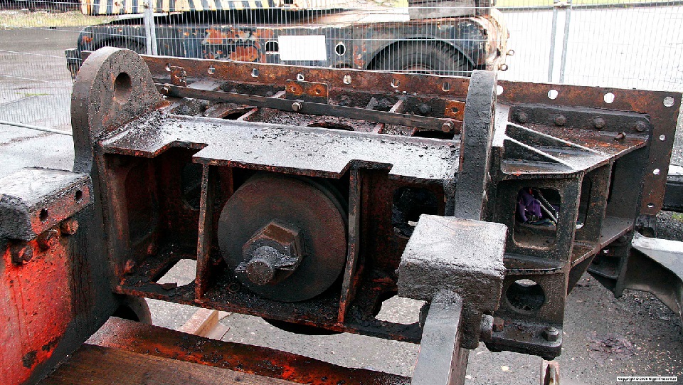
This is a photo of 70000's dragbox when under renovation in 2006. With thanks to Fraser Ker (http://www.fraserker.com/britannia/) for the reproduction.
Compare this photo with the picture of the dragbox for the Mark 2 system above and the differences at the front of the dragbox are apparent. In the dragbox for the Mark 3 system, the drawbar extends horizontally through the front of the dragbox. This reverts back to the design of the Mark 1 drawbar system with a drawbar spring.
The new dragbox and drawbar was a Swindon design and are covered by 5 BR drawings.
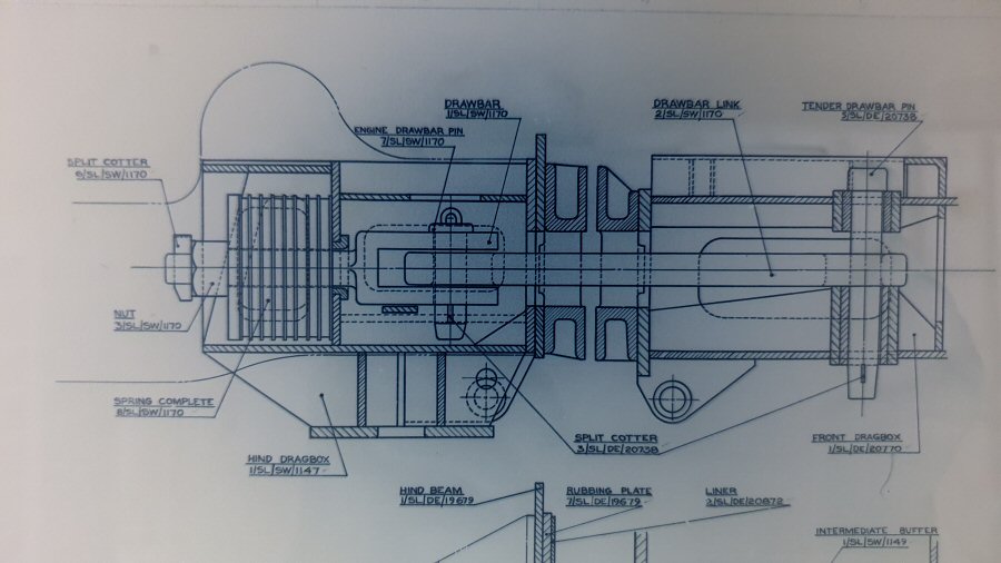
The arrangement drawing shows the engine dragbox to the left and the tender dragbox to the right. The drawbar is in 2 sections. The front (on the left) section has a threaded portion for the nut to compress the drawbar springs and a yoke on the rear end. A small pin is used to connect the front section to the rear section thus providing an articulated joint. The engine drawbar extends horizontally through a bush fitted in a vertical plate. The drawbar spring comprises of 5 Spencer Moulton drawbar springs, each separated by a large galvanised washer. A large nut and cotter are tightened up on an extra thick washer.
SSLC have created a 3D model of the dragbox for the Mark 3 system.

Conclusion
SSLC have concluded that we should adopt the Mark 3 drawbar system design. 72010 will be a higher powered Class 6 locomotive expected to operate at speeds compatible with the modern railway. SSLC have discusssed this Mark 3 design with Ricardo Ltd, our Assessment body, and they have agreed our proposal to adopt the Mark 3 system.
References
1 Bill Harvey's 60 Years in Steam - Chapter 13 - The Britannias
2 Harvey and RCTS A detailed history of the British Railways Standard Locomotives Volume 1
3 Locomotive Standards Sub-Committee Meeting Minutes September 1957 - minute 764
4 Locomotive Standards Sub-Committee Meeting Minutes June 1958 - minute 821
5 Locomotive Standards Sub-Committee Meeting Minutes September 1958 - minute 835
6 Locomotive Standards Sub-Committee Meeting Minutes January 1959 - minute 864