The Boiler - the Heart of Hengist
| If you would like to make a donation to the boiler fund, please click the button |
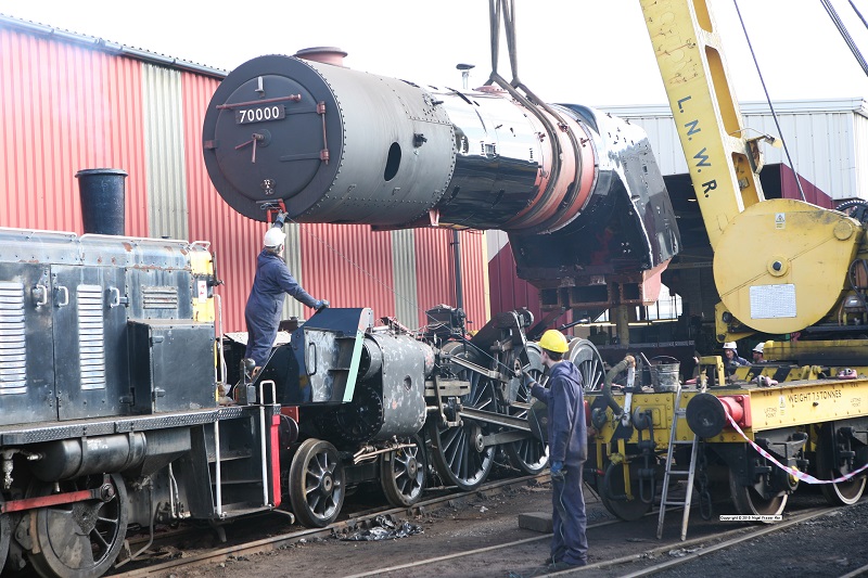
The image shows 70000 Britannia's boiler being installed at Crewe on 9 March 2010 - with thanks to the copyright owner Nigel Fraser Ker and his web site http://www.fraserker.com/britannia/ for allowing us to use this photo.
The boiler is the most complex part of a steam locomotive. At the front of the assembly is the smokebox, painted in matt black. Strictly speaking this is not part of the boiler; it is riveted to the boiler barrel. Behind the smokebox is the boiler. It consists of 2 parts
- The first part is a large parallel sided tube. In the photo it has been covered by the shiny sheet metal boiler clothing. Between this and the boiler shell will be fibreglass insulation matting.
- The second part is a tapered tube, smaller at the front and larger at the back. In the photo you can see the boiler shell. The clothing has not been fitted so that the lifting straps can be secured.
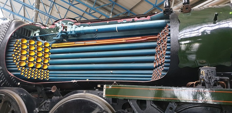
Within the 2 sections of the boiler barrel on a Clan locomotive there are 108 2 inch tubes and 35 5 inch tubes (dimensions approximate). These run the length of the boiler barrel and are fixed into tubeplates at each end of the boiler. The boiler is a fire tube boiler, in that the hot gases from the fire travel down the inside and water surrounds the the tubes. Thus the hot gases heat the water and generate steam.
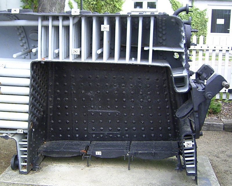
Attached to the rear of the boiler barrel is the rectangular shaped firebox. This is a box within a box. Inside the inner box is the fire. The inner box is separated from the outer box by a large number of stays.
Water fills the gap between the 2 fireboxes. The critical section of the inner firebox is the top, the crown sheet. This is the hottest part of the firebox and must be covered by water at all times. If the water level drops too far and the crown sheet becomes uncovered, then it will overheat and start to deform. Ultimately it will fail and there will be a boiler explosion.
Phase 1 - Lighting the Fire
| If you would like to make a donation to the boiler fund, please click the button |
©Copyright Christine Matthews and licensed for reuse under this Creative Commons Licence.
Modern legislation requires the boiler arrangement to undergo a properly controlled design and approval process prior to actual manufacturing.
We need and want to start this process NOW!
Cost and duration estimates are £60,000 and a maximum of two years.
Could we ask you to become a Steam Raiser and help "Light the Fire"? lf 200 members were to donate £250 each we would almost reach our target! Please consider making a contribution either as a one-off amount or, by regular staged payments if preferred.
The donation form can be found on this page and any donation, however small or large, would be greatly appreciated.
The design study will also cover any modifications, if any, would be appropriate for a 21st century locomotive. The following design changes have been agreed.
Riveting vs Welding
The boilers for the BR standard locomotives were constructed by riveting plates together. In contrast, the Southern Railway Merchant Navy and West Country class locomotives were constructed by welding plates together; this was 10 years before the BR standards were constructed. Riveting involves overlapping plates fixed together with rivets. Welding involves butting the 2 plates together (with a V shaped gap between the plates) and then welding them together. Virtually all modern boilers are manufactured by welding. Welding also offers a significant weight gain due to the lack of the overlap and no rivets. The project has now decided that the boiler will be an all welded boiler.
Firebox
The inner firebox for the BR standards was made from copper plate, reflecting the standard British approach to fireboxes at the time. Steel fireboxes were universal in America and widely used elsewhere; the 2 Southern Railway locomotive classes above had also used steel inner firebox. E.S. Cox, the design officer for the BR standard locomotives says that steel fireboxes were considered during the design and says "The choice was nicely balanced but the decision came down on copper mainly because with the indifferent and mixed qualities of water....."
A steel firebox is cheaper and lighter than a copper firebox with a significant difference in cost. However, without any water treatment, a steel firebox will only last a few years. This problem was encountered by the Southern Railway who then introduced a comprehensive water treatment system. Water treatment is being used with copper fireboxes in the heritage railway industry today to maximise the life of a boiler.
Steel does not conduct heat as effectively as copper. Therefore if a steel firebox was chosen, we would need to consider the volume dimensions of the water space between the inner and outer firebox. We cannot change the length of the boiler so any changes will need to be in the side legs. Changes would involve an increase in width of the outer firebox or a decrease in width of the inner firebox and a corresponding decrease in fire grate size.
After careful consideration, the inner firebox will be all steel..
Boiler Pressure
The Clip Report recommends an increase in boiler pressure. We have decided that the boiler will have a working pressure of 250 psi; an increase from the original Clans which operated at 225 psi. The Class 7 Britannia's boiler operated at 250psi. Our frames and motion are virtiually identical to the Class 7 and our frame stretchers are from the Class 8, 71000 Duke of Gloucester. The only significant difference is that the Class 6 middle driving axle is 9" diameter whereas the equivalent on Class 7 was 10". Our engineering team are looking closely at the fit and tolerances of the wheel on the axle. We have already evaluated that the higher boiler pressure will have no impact on the expected life of the bearing.
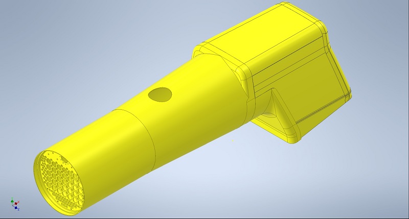
Our CAD modelling team have started work to convert all of the original British Railways drawings into a 3D CAD model. Keith has now got as far as the front tubeplate.


