


Clan Improvement Report (CLIP)
The Clan Project have commissioned a feasibility study from the Advanced Steam Traction Trust to apply the learning from the 5AT Project to the locomotive. The 5AT project was a conceptual design of true 21st century design for a modern steam locomotive.
Steam locomotive development effectively ended in Britain in the 1950's but elsewhere in the world notably, Argentina, South Africa and China, development continued for another 30 years. This knowledge together with the advances in materials and computer modelling of fluid flows will be used to optimise the design of 72010 (named as corporately acceptable) for main line running in the 2020's and beyond.
Specifically this will give exciting benefits in these areas :
- Cleaner and Greener - Optimised combustion improved drafting and gas flow will reduce coal consumption and emissions.
- More Powerful - Increased Boiler Pressure using modern steels for the boiler will allow a higher working pressure without increased weight moving more passengers quicker and cheaper, essential for main line operation on today's railway.
- More efficient - The original Clans were renowned for having the lowest coal consumption of any Standard Steam Loco. Improvements such as redesigned piston and valve rings will reduce water loss to reduce costs.
- Cheaper to run - Refined design - a holistic approach to provide many small improvements to the chassis plus optimised draughting of the wide firebox together with steam injection for clinker control allowing the use of lower quality coals - these type of coals maybe all that are available in the future
- Cheaper to Maintain - Improved design, materials and lubricants will give longer times between major services - we aspire to get to 30,000 miles between re-ringing
addressing all the of the problems of the 1950's and 1960's. Thus bringing onto the rails a Steam Locomotive fit for the 2020's!! - that still looks like the loco built in the 1950's
Within the report, particular emphasis was placed on realising the true potential of the design to improving its power and therefore its haulage (and thus money-earning) capacity. The 5AT project was a conceptual design of true 21st century design for a modern steam locomotive. The principal recommendations of the report were
1. Increase Boiler Pressure
The CLIP report considers an increase in boiler pressure from 225psi to 250psi. The premise behind this change is that the increase in nominal tractive effort would give rise to a useful increase in haulage capacity, and consequently revenue earning capacity. Increasing boiler pressure from 225 to 250 psi would increase the power delivered in 25% cut-off /60 mph from 1460 to 1630 IHP. The Specific Evaporation Rate required would be 580lbs/sq ft/hr, very comfortable, especially if redraughted. Tractive effort would increase to 30580lbs and the adhesion ratio at current axle loading would still be a very favourable 4.17, similar to the Britannia.
The boiler for the Britannia Pacifics was pressed to 250psi. Generally, the two boilers are very similar in terms of material, construction, plate thicknesses etc., as would be expected in a Standard range of locomotives. However there are some differences including firebox plate thickness and stay pitch. As the boiler build will be at the latter end of the project, we're still debating this one.
2. Installation of a Single Lempor Exhaust System
The first engineer to come up with the idea of directing the exhaust steam from the cylinders up the locomotive's chimney will always be hotly debated by railway historians. Some say Richard Trevithick, some Timothy Hackworth and others, George Stephenson. The combination of multi-tube boiler and steam blast are often cited as the principal reasons for the high performance of Rocket of 1829 at the Rainhill Trials. By using the exhaust steam, the harder the engine is worked (thus producing more exhaust steam), the stronger the pull on the fire. Too little blast and the potential of the exhaust steam is wasted. Too much blast and the draught is so fierce that it starts to pull the fire off the grate, down the tubes and out of the chimney.
In the first half of the 20th century, the British locomotive industry lacked facilities to scientifically test their designs. For this reason, in late 1934 Gresley took his new P2 design Vitry, France for static testing. In 1948, British Railways opened their own static testing plant at Rugby. Unfortunately, this facility came into operation at the in the twilight of British steam development. It did allow the exploration of the whole combustion/draughting cycle and did produce some dramatic results. The LMS class 2 2-6-0 (very similar to the BR version) was modified such that the maximum evaporation rate was changed from 9,850 lb of water per hour to 14,000 lb per hour - a significant increase. In other cases such as the Duke of Gloucester, the fundamental air/draughting problems were not tackled. The Clans were not tested on the Rugby plant.
One of the problems of the time was that the design team were loathe to apply the lessons learnt from the LNER (Kylchap exhaust) and SR (five-nozzle Lemaitre blastpipe) experiences.
Using a modern exhaust system can dramatically improve a locomotive's performance. The classic example is the Duke of Gloucester where design improvements and the fitting of a Kylchap exhaust turned a poor performer into one of the most powerful steam locomotives ever to run on Britain's railways.
The purpose of the exhaust system is to pump sufficient air through the boiler to allow the combustion of coal to convert its chemical energy into mechanical energy in the cylinders. The Advanced Steam Traction Trust have recommended the fitting of a simple Lempor exhaust system. This system has evolved from the work that has been undertaken on exhaust systems in the last 50 years. The Lempor Exhaust was initially described by Livio Dante Porta and Ing. Claudio S. Taladriz in their paper 'The Exhaust of Steam Locomotives' read in 1957 at the IX Pan American Railway Congress. It is a development of Porta's Kylpor Exhaust, which in turn was a development of the Chapelon's Kylchap. Porta came to prefer the Lempor because of lower friction losses in the system and simpler construction. The Lempor has fewer components than the Kylchap and Kylpor exhausts and is easier to align and install.
Components of the Lempor Exhaust
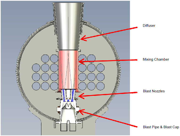
The Lempor Exhaust system consists of 4 major components:-
- Blast Pipe & Blast Cap - these are similar to the blast pipe and cap found on earlier exhaust systems, the principal difference is that the internal form is streamlined to guide the steam into the Blast Nozzles
- Blast Nozzles - there are 4 blast nozzles that give a multiple jet rather than the single jet found on earlier exhaust systems. The multiple jets :-
- Improve the mixing of the steam jet and the flue gas and as a consequence reduce the length of the mixing chamber that would be required compared to a single jet exhaust.
- Ensure optimum inlet flow conditions into the diffuser, by working with the mixing chamber to ensure a flat velocity profile for the steam and flue gas mixture entering the diffuser
During parts of release phase of the exhaust cycle, particularly at high steaming rates, the pressure ratio between the exhaust steam and the smoke-box pressure will have a pressure ratio greater than 1.83, when this happens the flow in the nozzle reaches sonic velocity at the narrowest part of the nozzle (the throat) thence accelerating to even higher velocity as it expands through the divergent section of the nozzle (following the principle of rocket engines). This very high velocity results in a very high smoke-box vacuum and high draft through the firebox - a momentary phase which disappears as soon as the exhaust pressure falls below the critical (sonic) value.
It is the (momentary) supersonic phase that creates a high smoke-box vacuum and which generates most of the draft, thereby obviating the need for the small nozzle area that would otherwise be needed to generate draft from the remainder of the exhaust phase. - Mixing Chamber - completes the mixing and exchange of momentum between the steam and the flue gas, so that there is a flat velocity profile for the mixture entering the diffuser, this is essential for operation of the diffuser. The steam and flue gas mixture slows down as mixing takes place and momentum is transferred from the steam to the flue gas, as a consequence there is a pressure rise in the mixing chamber.
- Diffuser - this slows down the steam and flue gas mixture even further and increases the pressure of the mixture, promoting flow and increasing the vacuum in the smoke-box even more.
The components of the Lempor; blast nozzle, mixing chamber and diffuser, working together allow the nozzle area to be made greater than on other exhaust systems, enabling it to deliver the required smoke-box vacuum at lower cylinder back pressure.
In order to accommodate the co-axial discharge of the vacuum ejector exhaust at the top of the chimney, it will be necessary to increase the diameter of the chimney slightly.
3. Remove Stress Raisers from the Frames
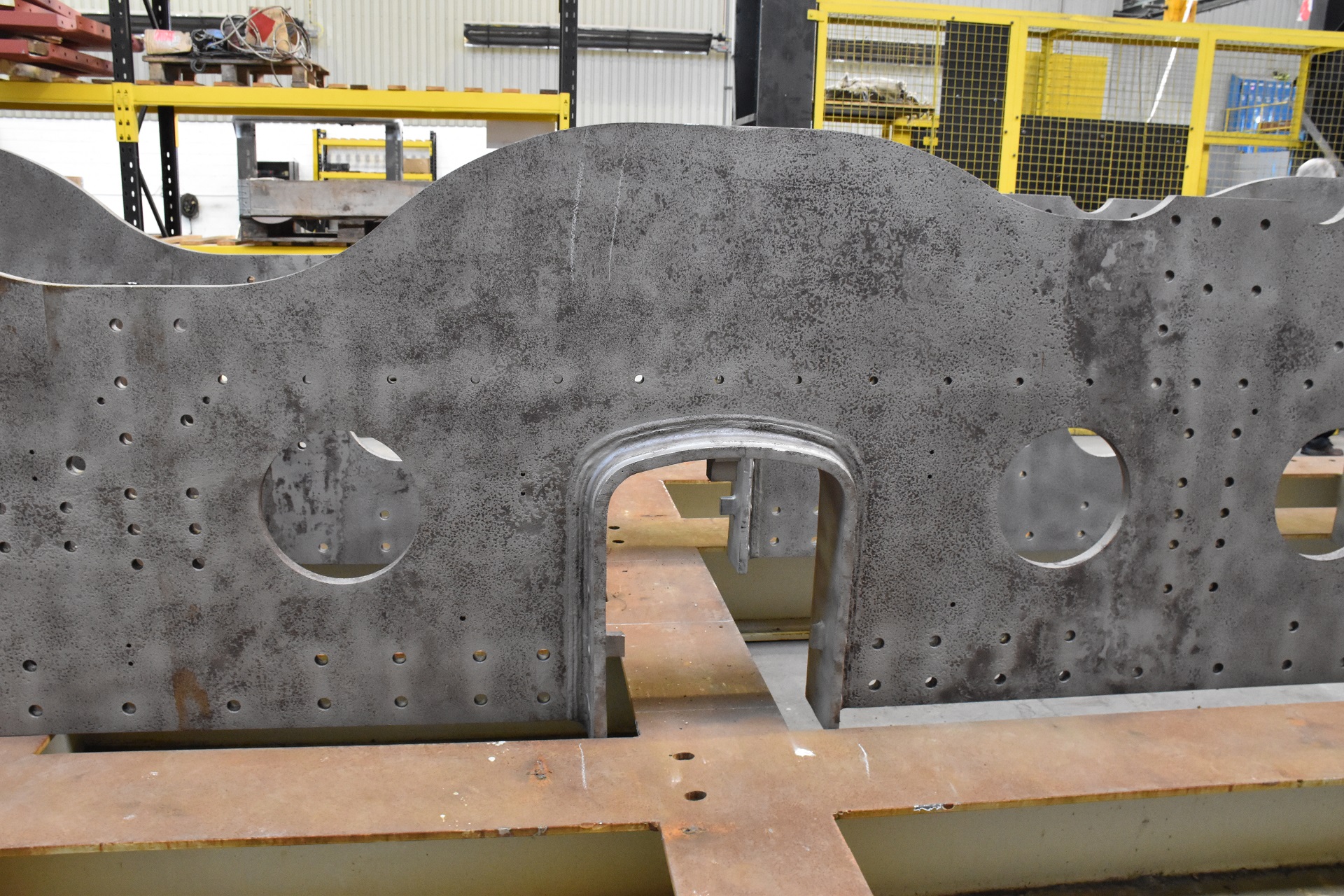
Whereas we don't have any knowledge of frame fatigue cracking on the Clan locomotives, fatigue cracking developed on the Britannia class after circa 438,000 miles of use (approximately 6 years at 73,000 miles per year). The main areas were above the rear bogie wheels, the top corner of the horn guide cut out and around the slide bar brackets. The horn guide area is shown in the photo below; the horn guides are not yet machined.
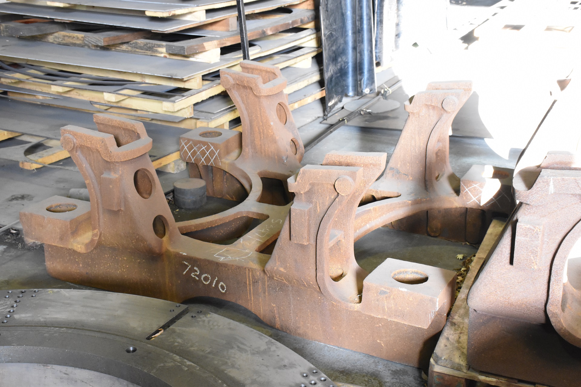
The horn guide problem area was recognised in the Lot 242 design in that the next batch of Clans were to be fitted with 3 off cast steel stretchers instead of fabricated stretchers. The cast stretchers were fitted to the Duke of Gloucester and better support the area around the horn guides. The photo below shows an upside down stretcher awaiting machining. The four 'legs' will support the main driving wheel springs.
4. Fit Multi-Ring Narrow Lightweight Piston Valve Rings including Bronze Ones
The CLIP report states "The benefits derived from the use of lightweight multi-ringed piston valves had been established some considerable time before steam locomotives started to be phased out of service. The fact that they had not been incorporated into any of the latter day UK designs may possibly be put down to the inherent parochialism of British design teams rather than any failure to register the advantages that they offer."
The attributes of a good valve design may be summarised as follows :
- As near-perfect 'breathing' through the port areas as possible.
- Minimum mass such that the inertia forces inherent from long-travel long-lap valves may be kept to the minimum thus promoting both longer life from valve gear bushings and lighter weight components in the gear train.
- Near-perfect steam tightness over extended mileages.
- Capable of manufacture within reasonably achievable tolerances and without recourse to special machinery.
The BR Standard valve head is a heavy casting mounted on a valve spindle which runs from the combination lever guide clevis, through the steam chest and into the front cover which houses an extended guide. The heads have a small clearance to the bore of the valve liners and due to the nature of their mounting are therefore 'suspended' within the steam chest.
Each valve head has six valve rings mounted with staggered gaps. All rings are prevented from turning by stop pegs.
From the above it can be seen that steam tightness is controlled purely by the ring condition as the valve head itself has a clearance within the liners. As the rings wear the ring gaps get bigger and the leakage path resistance decreases and the fewer rings per head the greater the leakage.
The CLIP report proposes a Porta type lightweight valve which uses a different mounting and increases the number of rings to 7 Cast Iron, interspersed with 3 bronze rings on each head. This is an interesting proposal that we will look into more closely when we reach that stage of the build.
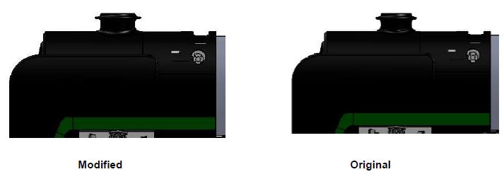
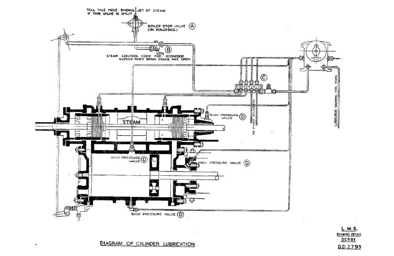
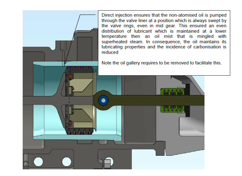
5. Adopt Direct Oil Injection rather than Atomisation for Piston Valve Lubrication
The lubrication of the piston valves and cylinders on the Clans was based on LMS practice with the addition of several L.N.E. and GWR features. The BR Standard system of lubrication for valves and cylinders utilised atomised oil via separate feeds into the piston valve and cylinder liners.
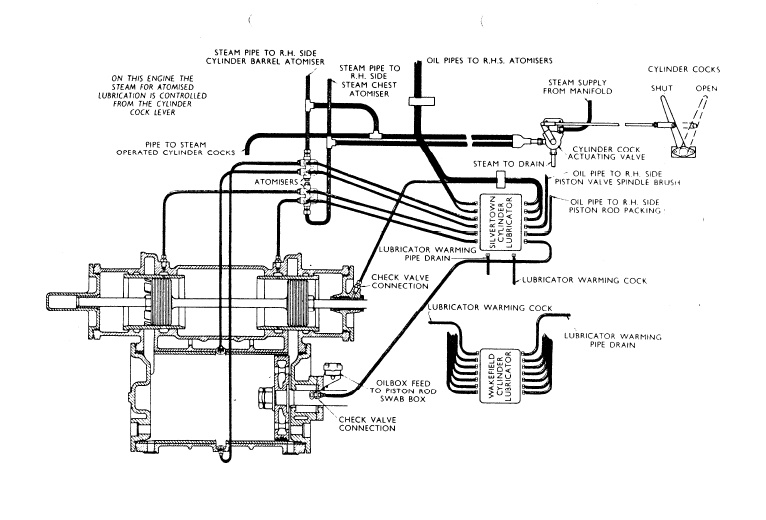
This contrasts with the LMS system that used atomised feeds into the piston valve liners and direct injection into cylinders.
There is evidence from several sources that BR Standards suffered lubrication problems leading to poor piston ring and piston valve ring wear. Nowadays there is much evidence to prove that the mixing of atomised oil mist with high temperature steam causes 'cracking' of the oil which both diminishes its lubricating properties and produces microscopic abrasive particles. The steam-chest and attendant valving, which is the region with the highest temperatures, suffers the most from this situation. There is however a well tried and tested alternative in the form of direct oil injection through the valve liner at a point which is always swept by the valve rings even in mid-gear.
The diagram illustrates the proposed change.
6. Steam Injection into the Primary Air Supply to Eliminate Clinkering and Improve Grate Life
Excessive temperature on a locomotive grate can increase the maintenance requirements of a locomotive. Ash can melt and as it solidifies it forms clinker, a hard material which impairs airflow through the fire grate and which can be difficult to remove, leading to poor steaming. . The grate itself also suffers wastage due to the high temperatures that it is exposed to. A technique to overcome this and also burn coal more efficiently was developed by Porta and used by Wardale on the SAR Class 26 No 3450 'Red Devil' is the Gas Producer Combustion System (GPCS).
The CLIP report has come out against a full GPCS implementation. Wardale reports that when working well, the GPCS had great advantages. However, the system was difficult to fire and need specific coal qualities. In the current preservation era, this would present challenges.
The CLIP reports says that consideration should be given to a semi GPCS system where controlled steam is directed to the grate by manifolds injecting steam into the primary air flow at the ashpan air inlets. This gives a degree of grate cooling and clinker control and has been applied on a number of narrow gauge engines in the UK.
7. A Number of Detail Design Changes to Improve on BR Standard Design Features.
The report covers a number of other areas; an important area is piston ring wear. BR7, BR8 and BR5 classes have piston ring lives of, on average, 10,000 to 12,000 miles and exceptionally 5,000 to 6,000 miles. This compares with 25,000 miles for latter LMS engines and 36,000 miles for re-built Bulleid Pacifics. NB the inside cylinder of the BR8 has a piston ring life of 25,000 miles. No evidence has been found that BR Standard locomotives fitted with double slidebars (i.e. the smaller classes) suffer from poor piston ring life. The inside slidebars of the BR8 are supported more robustly than the outer ones. Learning this and eliminating the type of atomiser fitted, leads to the root cause analysis of the poor piston ring life focussing on the Slidebar Bracket.
The larger classes used the three slidebar arrangement from the Gresley engines, this "elegant design" permitting a crosshead of minimum weight (the crosshead links the tail end of the main piston rod and the little end of the connecting rod. In this design the slidebars are above the crosshead only. For the smaller classes where they had to comply with the tighter loading gauge, this design would not fit in the space available and still give good bearing surfaces. Therefore the LMS design was used which has one slidebar above and another below the crosshead.
Also influencing the situation was the decision to adopt the Bulleid design where the frame spacing coincides with the centre lines of the axleboxes, this making the frame plates closer together. As the cylinders were as large as possible within the restrictions, this imposed considerable horizontal 'racking' forces on the slidebars.
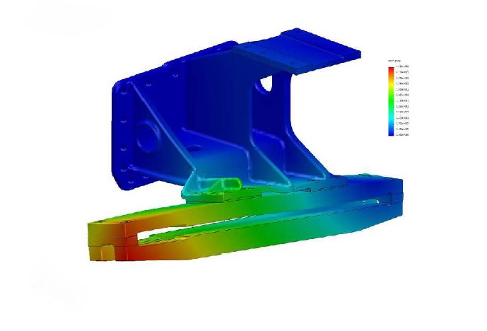
Nowadays, finite element analysis (FEA) is available to allow engineeers to diagnose the stresses on a structure. A first pass Finite Element Analysis of the bracket with typical loads shows that the front of the bracket deflects and twists about the slidebar longitudinal axis with a maximum deflection of circa 0.5mm vertically at the slidebar leading outer edge. This corresponds with the reports by D W Harvey, (ex Norwich Shedmaster in his book 'Sixty Years in Steam', Chapter 13) and Tom Daniels (designer of the British Caprotti Valve Gear) of BR7 and BR8 slidebars moving under load.
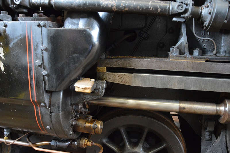
It can be seen that the slide bar bracket supports the centres of the slidebars and not the ends. The Caprotti Class 5 4-6-0s had a modification to the slidebars in that the front of the slidebar was attached to the rear of the cylinder.
The CLIP report recommends that we adopt this modification which would seem sensible given the results of the FEA. If the play can be reduced, then this should improve piston ring life.