| |
An in depth pre-production meeting to discuss the best procedure for assembling the frames of 72010 ‘Hengist’ was held at the premises of Riley & Son (E) Ltd on 21st October 2016. Present at the meeting were Colin Green from Riley & Son (E) Ltd (IRE), and John Graham, of Wayne Jones and Partners, our Vehicle Acceptance Body. Much use was made of the 3D printed model of the frames, produced by a member of The ‘Clan’ Project, which was set up during the meeting and proved to be an invaluable aid to discussions.
The outcome of the meeting has resulted in a considerable revision to the way the frame assembly will be carried out, with what we expected to be Phases I and II being combined into a single operation.
In the revised schedule, the main frame plates will be assembled, and all of the internal frame stretchers, ‘small bolting’ them together. The revision now envisioned, using best practice, will be to include the frame extension plates, dragbox, and various other small components, at the rear of the frame structure at this stage, rather than having them attached, separately, at a later date.
This decision was reached on the grounds of savings in costs and should, obviate the need for a further, potential, 3 month lead time before a ‘Phase II’ could commence. Combining these two processes will ensue that the Project’s momentum is maintained and not delayed by any lack of engineering availability on the part of our contractors.
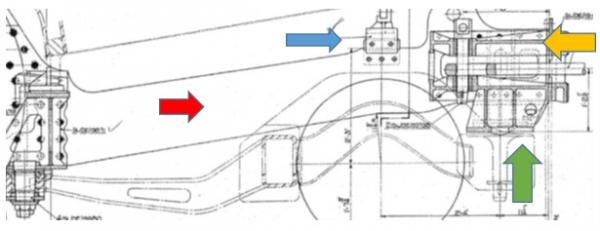
The diagram above shows these components..
The red arrow shows the rear frame extension, which is already in stock, and located at IRE.
The blue arrow shows the rear boiler mount. Two of these are required, one on each side.
The green arrow shows the trailing truck bolster, and associated gusset pieces. Again two of these are required, one on each side.
The gold arrow indicated the rear dragbox, with, below the arrow, part of the drawbar, which is not required at this stage.
Also required at this stage would be temporary frame keeps, to ensure rigidity of the structure during rotation and transportation. It is envisaged that these can be simple flat metal bars, of substantial dimensions, fitted with bolts of a smaller dimension than finished size, so that holes can be reamed to correct size when the final components are fitted.
Currently, tenders are being sought for the manufacture of all the components listed.
Once all the inside stretchers are in place, as well as the temporary frame keeps, and the whole ‘small bolted’ together, the assembly, carefully rotated by IRE, will be dispatched to Stephenson Engineering for machining of the Hornguide faces. Before this machining can be carried out, however, the correct frame keeps will need to be manufactured, machined and installed. This will ensure that what is a very complex frame structure is completely rigid before the Hornguides are machined to finished size. There are six frame keeps in total, four being to one pattern, the trailing pair being slightly different.
After the hornguide faces have been machined, the frame structure will be returned to IRE, turned the right way up, and the external frame components added. These will consist of the motion brackets, slidebar brackets, brake hanger brackets and the front buffer beam sub-assembly. These will again be ‘small bolted’ together initially, while the final alignment of all components takes place. The alignment will be taken from the centre of the hornguides for the centre driving wheel axle, which, as you will recall, will have been machined to finished size.
After it has been established that all alignments are correct, the small bolts will be removed progressively, and replaced using finished size fasteners. These will be supplied oversize, then machined to the correct finished size following reaming of the requisite hole to take the fastener. It is estimated that it will take approximately an hour to ream each hole to size, and there are 350 in each mainframe plate. This is obviously going to be a very time consuming operation.
At the end of the assembly process, the completed structure will be given a final shot blasting, and then be hand painted gloss black.
While this will result in long term cost savings, we need to raise additional finance, in the short term, to acquire and machine the required, additional, components. |


