hra fb twitter
sheffield
header

Main Cylinders

First First Previous Previous uparrow Back to Index Next Next Last Last
143 records found. Page 11 of 15 displayed.

For most of the photos on this page, you can click the image for a larger picture.

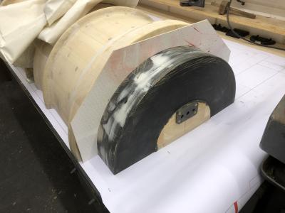
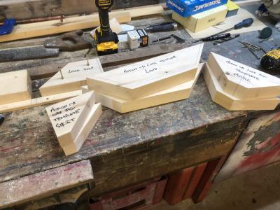
Highslide JS Here we see the pattern for the bottom section. Tony has marked the flange plate showing where the void has to be created. The piece on the left will form the "print" in the sand mould to support the core that will produce the void. These prints can be simple box sections with a taper "draw" so they can be pulled out of the sand mould.
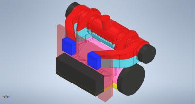
Highslide JS This image from our 3D model shows the "prints" that will support the "cores" in the pattern. The black circular extensions are the prints that will support the valve and motion cylinder cores. The rectangular black print will support the core making the void in the lower half of the pattern. You can see how they have been designed to get the centre of gravity of the core in the right place so that the core does not topple inwards. The blue prints are for the exhaust steam passage cores.
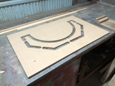
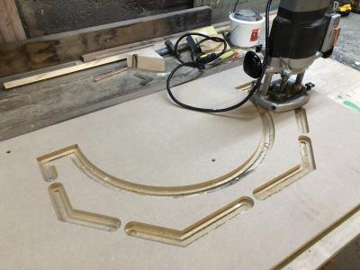
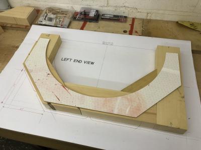
Highslide JS March 2021. Tony has now had his jig manufactured for creating the core for the the motion cylinder. Remember that the core will be a solid tube of sand mould so the pattern has to be a negative of this - as we need to create concave curves, we can't create it in a lathe. The jig is a router guide - a guide bearing on Tony's router engages in the slots in the jig which has been created from Keith's drawing.
Highslide JS Here is the jig in use on a scrap piece of hardboard to check that the theory works
Highslide JS Check the test piece on the print end of the motion cylinder pattern proves that the theory works.
Highslide JS The final stage before production starts was to assess the mock up of the glue up of the off cuts of Quebec Yellow Pine to make a bench jig for "mass production" of the core sections. The image illustrates this for two ways of gluing up the bits. Tony is going for the one on the left side of the image as he thinks this will give him the most strength in the overall box assembly.
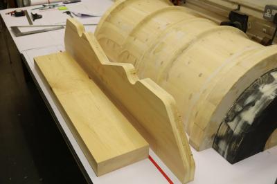
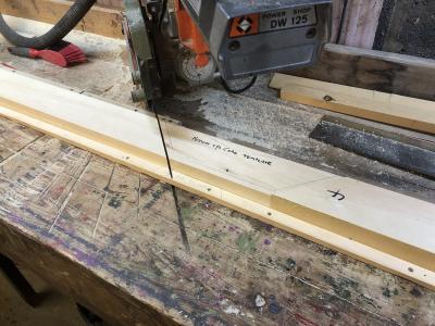
Highslide JS Now to start cutting the sections for the core boxes. The image shows a simple bench guide and and 'stop' for repetitive cutting.
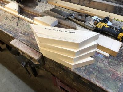
Highslide JS This image illustrates the result of simply feeding timber along the bench guide and making the cut. Tony can quickly build up a pile of sections. The pencil markings are the final dimensions of the core boxes after routing to size.
Highslide JS A complete set of sections
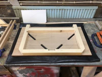
Highslide JS This is the gluing jig. Tony says "One necessary job was to add 'squeeze drains' to take care of the glue squeeze. In my jig, the glue runs through the baseboard on to a black poly mat." These are the various slots that you can see.
First First Previous Previous uparrow Back to Index Next Next Last Last
143 records found. Page 11 of 15 displayed.