Pony or Trailing Truck
| Back to Index | Next | Last | |||||||
| 11 records found. Page 1 of 2 displayed. | |||||||||
For most of the photos on this page, you can click the image for a larger picture.
The "2" in the 4-6-2 Pacific locomotive wheel arrangement is the 2 wheel truck that supports the weight of the rear of the locomotive. This truck can be known as a
Pony Truck
Trailing Truck
Delta Truck (as the weight is taken on 3 points)
In some of the British Railways meeting meetings it is also referred to as a Bissel truck
The British Railways drawing use the term "pony truck" so that is the term used here. The Class 7 Britannia locomotives and the original Class 6 Clan locomotives were fitted with a leaf spring pony truck. This had limited room for movement and was reported to give a hard ride. The solitary Class 8 locomotive - 71000 Duke of Gloucester was fitted with a longer travel coil spring pony truck which is reported to assist in providing a very smooth ride. This pony truck was part of the drawing set for the lot 242 Clans.
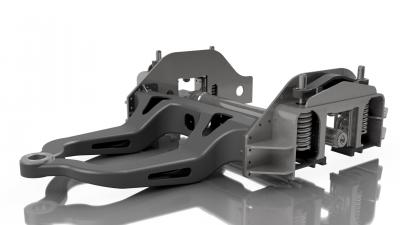
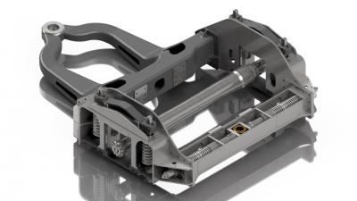
Philip Atkins in his book "Britannia - Birth of a Locomotive" provides details of the evolution of the pony truck design. The pony truck consists of 4 primary components
- The radial arm which has the main pivot bush and is bolted/riveted to the other frame components. The pivot bush takes some of the weight of the rear of the engine.
- 2 off side frame plate assemblies
- 2 off "Up and Over" I section stretchers fitted between the radial arm and the hind stretcher
- A hind stretcher fitted between the side frame plates. This contains the side control gear consisting of 2 pairs of coil springs.
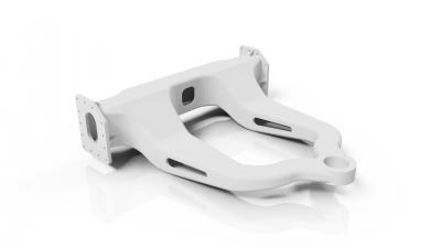
The design originated from the Southern Railway "Merchant Navy" class. Initially these were cast steel but fabricated versions were built after the Second World War. The Britannias and Clans had an all fabricated pony truck but by late summer 1952, problems were being experienced with fractures adjacent to the pivot pin. Stiffening plates were welded in in this area to overcome the problem. However a new design was evolved in 1953 using coil springs instead of laminated, leaf springs and a cast steel radial arm. This design was fitted to 71000 - Duke of Gloucester. It was intended for the last batch of Britannias but was never implemented. The design was specified for the Lot 242 Clans.
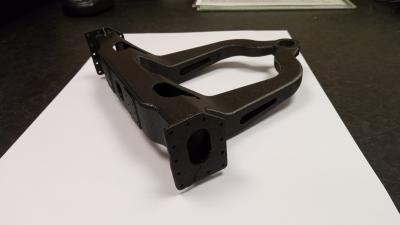
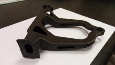
We are grateful to Michael Hughes from the BR Class 8 Steam Locomotive Trust for the reproduction of the following photos which show the pony truck from 71000 which we will need to manufacture.
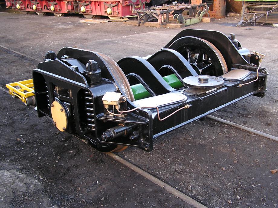
This is a rear view of the pony truck. The coil springs are shown, either side of the outside Timken taper roller bearing axle box. The 2 oval plates are the weight bearing areas; 2 bolster cups "float" on here which engage with bolster domes fitted at the rear of the locomotive frames. Between the 2 plates is the centring pin. This pin is bolted to the dragbox at the rear of the frame extensions and engages in a slot on the pony truck. 4 side control springs (2 either side of the pin) control the movement of the pony truck on entering curves and help recentre the truck leaving a curve. The 2 oil boxes lubricate the centring gear bushes. You can see the end of the centring gear protruding below the oil box. We have the oil box brackets in stock
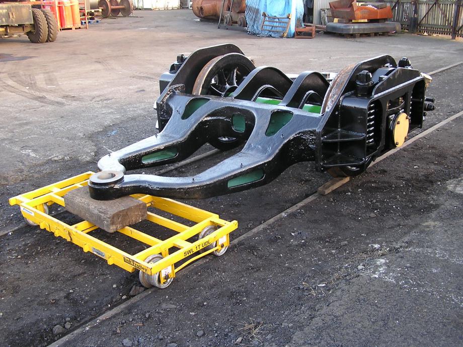
This is a view from the front of the pony truck showing the central front pivot. The triangular front section of the truck is a casting, the rear section is a fabrication.
| Back to Index | Next | Last | |||||||
| 11 records found. Page 1 of 2 displayed. | |||||||||


