


You can click on some of the pictures on this page to see a large size version.
Cab
The cab is attached to the locomotive in 2 places.
- The front of the cab floor is attached to the bottom of the firebox backplate. 4 threaded snubs are welded to the backplate and "U" brackets ar attached to the floor support and the snubs.
- The rear of the cab floor is attached to the hind beam of the locomotive frames via a diaphragm plate. The diaphragm plate is the width of the cab floor and is about 13 inches or 330 mm high. It consists of 2 sheets of 1/4 inch plate (6mm) fastened together. As the boiler expands, and the cab is attached to the boiler/firebox, the diaphragm plate has to allow for that expansion by bending backwards.
The picture below shows the diaphragm plate of 70000 while under overhaul. The diaphragm plate is a slightly different design to the one intended for the lot 242 class 6.

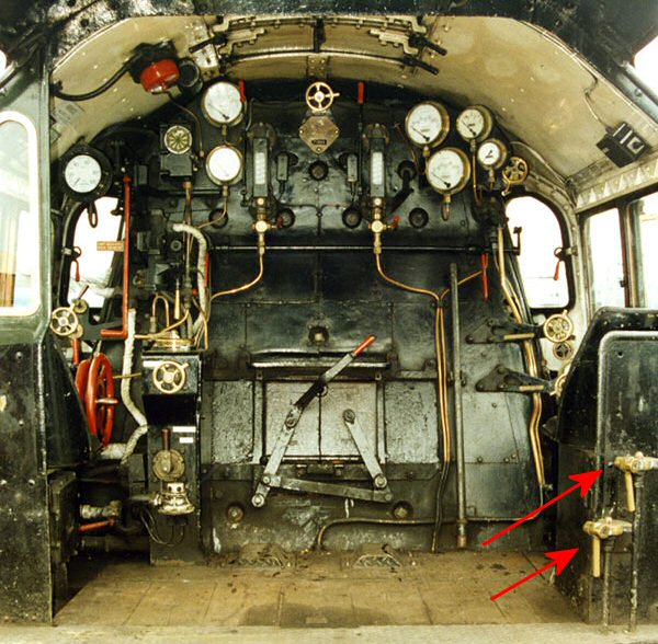
Considerable effort by British Railways was made at the design stage to provide an optimum cab layout for the BR Standard Locomotives. E.S. Cox reported [1] :-
We evolved, therefore, a footplate layout not exactly following any one region, but developing as far as possible features supported by the majority of Motive Power Department and Trades Union members whom we had consulted. We tried to arrange the firebox face in as uncluttered manner as possible, with steam supplies coming from a common fountain (i.e. manifold) outside the cab, and with all controls appropriate to the driver and fireman grouped on their respective sides of the cab. In order to subject these proposals to the most realistic examination and criticism by prospective users, a full size mock-up of the whole back end of the engine and front of the tender was built in Derby Works.
He continued :-
The remaining novel feature of this cab demonstration was the extension of the floor right up to the tender front by means of cantilever supports from the boiler, thus providing a firm platform for the fireman, and eliminating the too mobile fall plate between engine and tender which was a feature of previous practice. We did not foresee at this time that so admirable an improvement would before long draw down a measure of trouble upon our unsuspecting heads.
The advantage of this system was demonstrated when Britannia No 70012 John of Gaunt on 9 August 1957 broke the drawbar pin (the drawbar being the connection between engine and tender) which resulted in the engine being separated from the tender, and the train. The vacuum brakes on the tender brought the train to a stand but as the engine was steam braked the engine, less tender, continued on its way. Bill Harvey, shedmaster at Norwich, said [2] :-
The fireman probably owes his life to the design of the Britannia cab footplate that extends right back to the tender front; had it been the usual arrangement with a hinged fall plate between locomotive and tender on which he was standing when the locomotive broke loose he would have been thrown under the tender wheels.

In the photo above, courtesy of Paul Orrells and Nigel Fraser Ker, it can be seen that the gangway doors are hinged on the locomotive. 2 handrails, either side of the door, extend down from the cab roof to the cab support, under the cab floor. Note also the concertina sheeting fitted between engine and tender.
Problems with draughts in the cab emerged soon after the engines were introduced into service. A Scottish Region Report on Class 6 performance [3] stated:
As is the case on the Class 5 B.R. Standard engines, when the class 6 engines are running at speed a severe draught is projected from both sides across the engine footplate rendering the conditions most uncomfortable and it is unfortunate that from the point of view of the enginemen this somewhat nullifies the advantages accruing from the new cab design.
The Chief Draughtsmen Meeting of January 1952 states [4] :
Investigations so far carried out had localised the undue draught to air coming up between engine and tender and striking the shovelling plate above which it causes eddies in the position adjacent to the tender front. Means or improvement are still being experimented with and a further report will be submitted.
The minutes of the Chief Draughtsmen Meeting and its successor, the Locomotive Standards Sub Committee, report on various attempts to solve this problem. Draught Screens between engine and tender were installed and various materials were tried out - canvas, "U" section rubber, Plasticised Fabric Glassweave and Neoprene Covered canvas. Class 6 drawing SL/DN/C/557 shows concertina draught seals made out of Glassweave Plasticised Cloth with a similar profile to that used in modern inter carriage connections. In October 1952 the Chief Draughtsmen Meeting reported that [5]:
Two schemes tabled by Derby were discussed for more permanent form of draught prevention using fall plate and gangway doors. One of these looked promising and it will be developed further; as soon as the arrangement is agreed it is proposed that a new B.R. tender engine out of current production should be fitted up for trial.
Unofficial modifications included "A practical solution to the problem was found at Stratford by inserting a disc board between the seat back and cushion to effectively extend the height of the back of the seat. [7]. This is relevant to one of the changes proposed for 72010.
Cab for 72010 Hengist
The cab specification for the lot 242 Class 6 included [6] :-
- Fall Plates between Engine & Tender.
- Gangway Doors.
- Opening Front Windows.
- New Cab Supports
The later type of cab can be seen in the photo below.

Note that the doors are no longer hinged on the locomotive. The doors are now hinged on the tender and consist of a 3 plate folding system. The rear handrail attached to the cab roof is removed and replaced by a shorter handrail fixed to a plate on the tender. Note also the upwards extension of the driver's backplate including a rear view window. This backplate was fitted to 71000 "Duke of Gloucester" and at least some of the 9F locomotives (92200 "Evening Star" has this type of driver's backplate).
We have not been able to locate the drawing for the Lot 242 cab arrangement so the cab for 72010 will be a combination of the original lot 221 Class 6 cab drawing, the last batch of class 7 cab drawing and the cab drawing for 71000. We do have some of the other cab drawings including the revised cab support (i.e. essentially the floor and supporting structure. The following main changes are included :
1. Fall plate, handrails and tender doors. As seen in the photo of 71000 above.
2. Full height driver's back panel as fitted to 71000 and other BR standard locomotives. We have been told that this does reduce draughts. The class 8 cab arrangement shows the dimensions which may need modification to fit with 72010's cab profile. The drawing for the window is available.
3. Repositioning of Feed Water Valve operating handle for the exhaust steam injector.
In the original class 6 design, the operating handle to control the feed water valve for the exhaust steam injector was positioned in front of the fireman's seat. The operating handle for the live steam injector water valve was positioned right at the back of the cab on the fireman's side. For the lot 242 design, both operating handles were to be fixed to the rear of the back panel behind the fireman. The layout can be seen in this photo of 71000 (courtesy of the BR Class 8 Steam Locomotive Trust)
The drawing is available for this change.
4. Ashpan
For the lot 242 Class 6, the ashpan was redesigned. One of the main changes was to add an additional rear door with its own control hand wheel. The lot 221 class 6 had one operating handwheel and bracket located low down on the front of the fireman's side of the cab. The photo below of 71000 (courtesy of the BR Class 8 Steam Locomotive Trust) shows the revised arrangement.
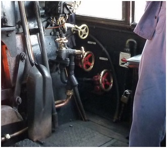
The ashpan door operating handwheels have red spokes. The upper handwheel operates the 3 doors at the front of the ashpan (the same as the lot 221 design). The handwheel operates a shaft running forward through the cab front plate to a bell crank mounted on the side of the firebox. The lower handwheel is the change and this operates the single door at the rear of the ashpan. The handwheel operates a shaft that runs down at an angle to a bell crank, inside the cab, that then transmits the motion via a shaft which goes through the cab floor. Although we have most of the drawings we are missing the drawing that specifies the location for the rear ashpan door bell crank bracket. The bracket is bolted to a pad which is welded to the side of the cab. The bell crank and bracket are different to the system used on 71000 so we will need to do some reverse engineering of 7100 drawings to determine exactly where the bell crank needs to be positioned.
5. Other Changes
As we are building a boiler with a steel inner firebox as opposed to the original copper inner firebox, the firebox shape will be different. We need to add additional water volume between the inner and outer fireboxes. This will mean that shape of the firebox will be different. Until the design of the boiler and firebox (including clothing) is finalised, we cannot complete the design of the front of the cab floor and the profile of the cab spectacle plates.
References
1 E.S. Cox - British Railways Standard Steam Locomotives
2 Bill Harvey's 60 Years in Steam - Chapter 13 - The Britannias
3 The Railway Executive (Scottish Region) - Report on the Performance of the B. R. Standard Class 6 4-6-2 Mixed Traffic Locomotive in the Scottish Region
4 Chief Draughtsmen Meeting Minutes January 1952 - minute 6
5 Chief Draughtsmen Meeting Minutes October 1952 - minute 114
6 Locomotive Drawing Office, London Road, Derby - British Railways Standard-Class 6 2 Cyl. 4-6-2 Mixed Traffic Locomotive Lot 242
7 RCTS - A Detailed History of British Railways Standard Steam Locomotives - Volume 1