Lot 242 Class 6 Design
British Railways built their steam locomotives in batches, identified by lot numbers. The lot numbers for the Class 6 Clans and Class 7 Britannia locomotives built by BR were :-
| Lot Numbers | Class | Engine Numbers |
|---|---|---|
| Lot 220 | Class 7 | 70000 - 70024 |
| Lot 221 | Class 6 | 72000 - 72009 |
| Lot 228 | Class 7 | 70025 - 70044 |
| Lot 234 | Class 7 | 70044 - 70054 |
Although we have most of the drawings for the lot 242 Class 6, we have not been able to find much of the design documentation, the reasoning behind the changes. We do have one document from the Derby Locomotive Drawing Office, dated 22 April 1954, titled " Summary of Work to be Done in the Locomotive Drawing Office on 22/4/54.". The document covered the lot 242 Class 6 that was programmed to be built, the final batch of class 7 Britannia locomotives and modifications to the solitary Class 8 locomotive, 71000 - Duke of Gloucester.
The document sets out the changes required for the lot 242 Class 6 locomotives. The original text from the document is shown in italics and our comments are in plain text.
Boiler Section.
B.R. Standard 4-6-2 Class 6 Locomotives. Lot No 242.
New ashpan arrangement and details embodying improvements in design as follows: -
1. Incorporating Rear Door with Operating Gear.
The original Clan locomotives had 3 ashpan/damper doors fitted at the front of the ashpan, operated by a single cross shaft and linkage to an operating wheel in the cab (fireman's side). This was as a result of a decision taken at the April 1951 Chief Draughtsmen's Meeting which stated "Rear Ashpan Door - Following further experience, these doors to be bolted up on 1951 Class 7 engines. Doors to be eliminated for future engines."
However, this decision was reversed in April 1954 and the lot 242 ashpan drawings shows a ashpan door at the rear of the ashpan in addition to the 3 doors retained at the front. The rear ashpan door was to be operated by an additional handwheel in the cab. As we do not have the cab arrangement drawing for lot 242, we will be using the details shown on the cab arrangement for 71000 to determine where the necessary bracket pads are fitted.
2. Providing additional clearance between ashpan operating gear and pony truck reigns.
We believe that there is a spelling mistake and it should say "pony truck reins". These are the arms at the front of the pony truck going from the pony truck frame to the central pivot. Problems had been reported in the Chief Draughtsmen's Meeting minutes detailing fouling problems between the ashpan and the pony truck.
3. Providing additional stays to prevent warping.
We can discount the change for 72010 Hengist as we will be fitting a steel inner firebox so the staying arrangement will be different to the original.
4. Improving Operating Gear for Hopper Doors.
Hopper door distortion is mentioned in the Locomotive Standards Sub Committee meeting minutes (successor to the Chief Draughtsmen's Meeting). The change seems to be stiffening ribs added to the hopper doors, presumably to avoid distortion from hot ash.
Scheme to improve steaming and new experimental chimney to be designed.
The lot 242 drawing sets include a new drawing for the chimney. A different chimney will be required following the CLIP report - see section on CLIP report in design section.
Boiler Mattress Arrangement drawing to prepare.
We have not been able to locate the mattress drawings for class 7 or Class 6. There is a mattress drawing available at the National Railway Museum. It is likely that we will have to develop our own mattress drawing using modern insulation materials.
Frame Section.
B.R. Standard 4-6-2 Class 6 Locomotive. Lot No 242.
New Frame Arrangement incorporating Frame Cross Stretchers as on B.R. Class 8.
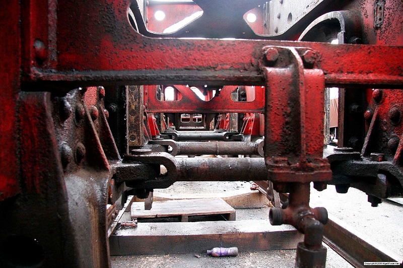
In the original Class 6 and 7 design, the spring hanger brackets were individual castings, bolted to the frames and kept apart by cross shafts, pin jointed to the spring hanger brackets. The arrangement can be seen in this photo of 70000, Britannia.
Thanks to the copyright owner Nigel Fraser Ker and his web site http://www.fraserker.com/britannia/ for allowing us to use this photo.
Although we have not been able to find any documentation on frame failures in the Class 6 Clans, Bill Harvey in his book "Bill Harvey's 60 years in Steam" provides considerable detail and diagrams. Bill Harvey was the shedmaster at Norwich, responsible for running the fleet of Britannias on the Great Eastern mainline.
The first design change in 1952 was to replace 2 spring hanger brackets (on each side of the frames) and the connecting cross shaft with a single steel casting.
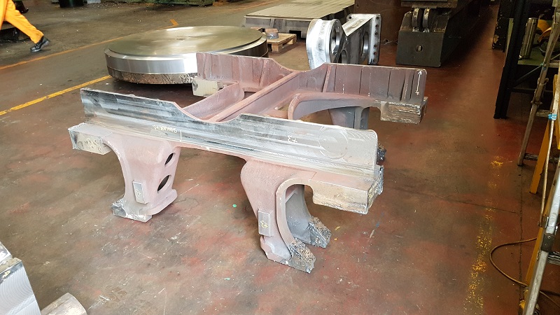
The next design change in 1953 for 71000 - Duke of Gloucester was to combine 2 of the spring hanger castings into a single Combined Frame Stretcher and Spring Bracket casting. This photo shows the casting that sits between the leading driving wheel and the central driving wheel.
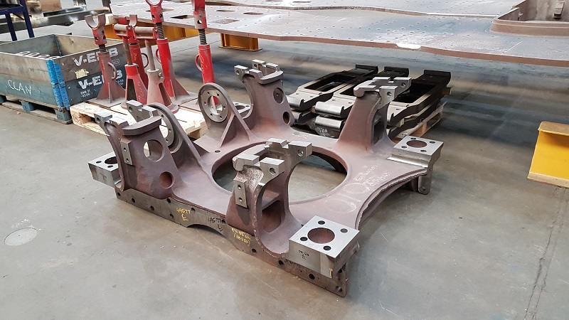
The photo was taken during initial machining operations at CTL Seal. 2 of these "4 legged" castings are required, the one between the central and trailing driving wheels is different in that the casting also supports the main brake shaft as seen in this photo (casting is upside down)
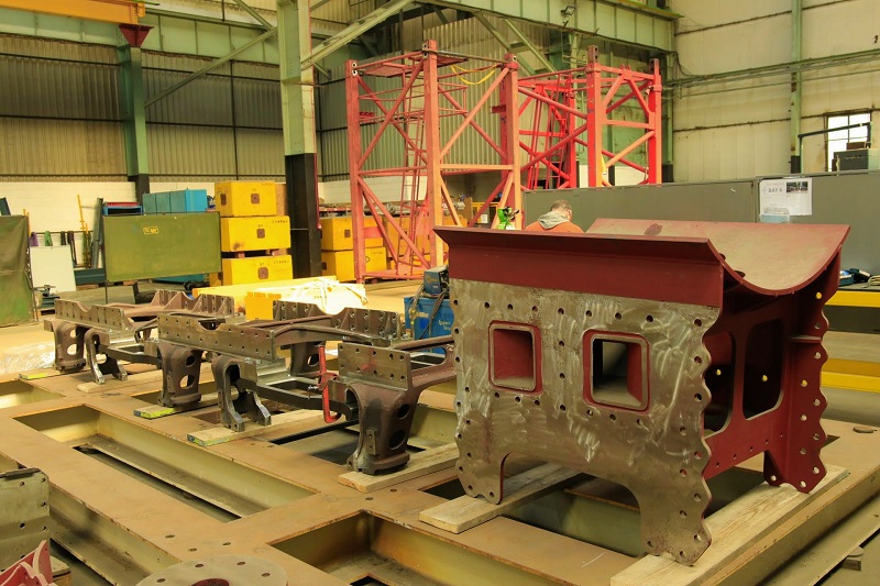
The front Combined Frame Stretcher and Spring Bracket can be seen in this photo setting up the stretchers in preparation for fitting the frame plates.
New Slotting & Drilling drawings required.
Obviously, this is a major change. We have the drawings for slotting and drilling.
New Design Brake Cylinder Support.
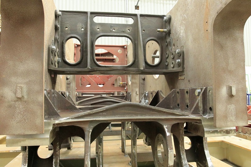
A new design of Combined Frame Stretcher & Brake Cylinder Support was developed especially for lot 242. The brake cylinder support stretcher is the top stretcher in this photo.
Alteration to rubbing surfaces etc., on side control gear on Pony Truck.
Although not actually mentioned in the document, but clearly shown on various lot 242 drawings, the intention was to replace the leaf spring version of the pony truck fitted to all Class 6 and 7 locomotives with the coil spring version fitted to 71000 - Duke of Gloucester. The leaf sprung version had been shown to give an uncomfortable ride whereas the coil sprung version is a considerable improvement. The other major change in the pointy truck was to replace the fabricated radial (or delta) arm with a cast version. The BR meeting minutes have a number of references to cracking of the radial arm frame around the pivot. Further details of the lot 242 pony truck can be found on this page .
Motion Section.
B.R. Standard 4-6-2 Class 6 Locomotives. Lot No 242.
Complete marking-up of drawings and issue of same to Crewe.
There are no major, lot 242 specific changes in the motion area. Most of the changes had been fitted to the original lot 221 Clans during overhauls. Examples include:-
- Rectangular form coupling rods to replace fluted coupling rods.
- A cylinder enclosure around the main reversing gear spring, seen on fireman's (right) side of the locomotive.
- Revised bolting arrangement for the slidebars following the January 1960 Settle rail accident.
Pipe & Rod Section.
B.R. Standard 4-6-2 Class 6 Locomotives. Lot No 242.
New Pipe & Rod Arrangement incorporating :-
1. Atomiser steam controlled by Cylinder Cock Actuating Valve.
Another change that had been made to lot 221 Clans. Lubrication to the cylinders is provided by cylinder oil atomised by steam. In the original design, the atomiser steam control had been linked to the regulator handle as in GWR practice. This relied on drivers opening the regulator slightly when coasting. However enginemen on other regions long used to firmly shutting the regulator when coasting resulted in excessive piston ring wear, especially when descending long gradients. This change moved the control to the same lever as the Cylinder Cock Actuating Valve.
2.Revised Injector Gear due to new Ashpan Arrangement.
The injector brackets are bolted to the underside of the firebox foundation ring and to the sides of the ashpan. Therefore minor modifications were required.
3. Revised Sanding Arrangement due to removal of 'Downs' Sanding.
The 'Downs' Sanding system was fitted to the original class 6 and 7 locomotives. This used steam heated coils within the sandboxes to keep the sand dry. From the BR meeting minutes, it is obvious that other regions had a number of problems with reliable sanding. In the end, the 'Downs' system was removed from the sandboxes. One other change was to add an additional sandbox (to the 2 already fitted) to service the leading driving wheels. The original design used a long, mainly nearly horizontal set of pipes to service the front wheels.
New Lubrication Pipe Arrangement incorporating:-
1. 2-Feed Atomisers in place of 4-Feed Silvertown Atomisers.
The lot 242 lubrication arrangement shows a pair of 2 feed atomisers on each side of the frames, each pair served from its own Silvertown lubricator. 70013 - Oliver Cromwell - also has this arrangement. The original design must have been one 4 feed atomiser on each side. In the pair of 2 feed atomiser system, each atomiser gets its steam from a separate pipe system - although both pipes ultimately lead back to the single Cylinder Cock Actuating Valve.
2. Pipes re-arranged to suit.
Obviously, the pipework is slightly more complicated with the revised system.
New Blow-off Cock Arrangement due to New Pony Truck.
The blow-off cock is an Everlasting Blowdown Valve from the Everlasting Valve Company - still in production. The blow-off cock is sited on the front bottom of the firebox and is used when on shed to clear out any deposits that have settled in the bottom of the firebox water spaces. The steam is ejected through a silencer. It is probable that this change related to the routing of the silencer pipework - we have the drawing for this.
Arrangement & Details of Smith-Stone Speedometer Equipment.
The RCTS book on the BR standards States that speedometers were fitted to 6 of the 10 original Clans and does not have the fitted date for the remaining 4. Speedometers were being rolled out to most steam locomotives in this period. We have the drawings for the speedometer arrangement.
Cab & Tank Section.
B.R. Standard 4-6-2 Class 6 Locomotives. Lot No 242.
New Cab Arrangement & details incorporating:-
1. Fall Plates between Engine & Tender.
2. Gangway Doors.
3. Opening Front Windows.
4. New Cab Supports.
The cab changes are described on the cab section within the design pages. Follow this link to read the details. Suffice to say that the original cab design with no fall plate, coupled to a BR1 tender (follow this link for details) had encountered serious problems with draughts. The revised design required a fall plate and a different design of tender. We believe that the first 5 batch of lot 242 Clans were to be fitted to BR1B tenders with a higher water capacity for the Southern Region where they were destined.


